


5-20
S
uperWorkstation 7045A-C3/7045A-CT User's Manual
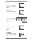
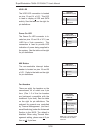
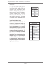
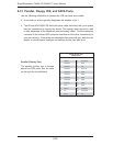
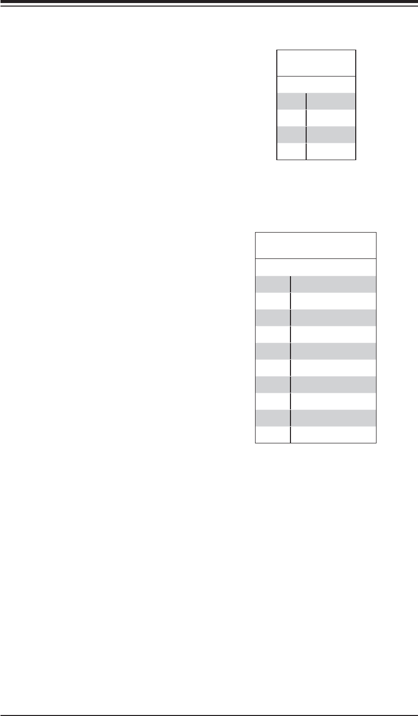
CD Header Pin
Defi nitions (CD1)
Pin# Defi nition
1 Left
2 Ground
3 Ground
4 Right
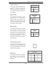
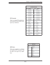
Front Panel Audio Pin
Defi nitions (JC2)
Pin# Defi nition
1MIC_L
2 Audio Ground
3MIC_R
4 FP Audio Detect
5 Line_2_R
6 Ground
7 FP_Jack Detect
8Key
9 Line_2_L
10 Ground
CD Header
A 4-pin CD header (CD1) and a
Front Panel Audio header (JC2) are
included on the serverboard. These
headers allow you to use the on-
board sound for audio CD playback.
Connect an audio cable from your
CD drive to the CD header that fi ts
your cable's connector. Only one
CD header can be used at any time.
Front Panel Audio Control
When front panel headphones are
plugged in, the back panel audio out-
put is disabled. This is done through
the FP Audio header (JC2). If the front
panel interface card is not connected
to the front panel audio header, jump-
ers should be installed on pin pairs 1-2,
5-6, and 9-10 of the Audio FP header.
If these jumpers are not installed, the
back panel line out connector will be
disabled, and pin 1 of the microphone
in will be left fl oating, which can lead
to excessive back panel microphone
noise and crosstalk. See the table at
right for pin defi nitions.