


5-2
S
uperWorkstation 7045A-C3/7045A-CT User's Manual
Unpacking
The serverboard is shipped in antistatic packaging to avoid electrical static dis-
charge. When unpacking the board, make sure the person handling it is static
protected.
5-2 Serverboard Installation
This section explains the fi rst step of physically mounting the X7DCA-3/X7DCA-i into
the SC743TQ-865-SQ chassis. Following the steps in the order given will eliminate
the most common problems encountered in such an installation. To remove the
serverboard, follow the procedure in reverse order.
Installing to the Chassis
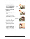
Access the inside of the system by removing the screws from the back lip of
the side cover of the chassis, then pull the cover off.
The X7DCA-3/X7DCA-i requires a chassis big enough to support a 12" x 13"
serverboard, such as Supermicro's SC743TQ-865-SQ.
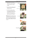
Make sure that the I/O ports on the serverboard align properly with their
respective holes in the I/O shield at the back of the chassis.
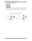
Carefully mount the serverboard to the serverboard tray by aligning the board
holes with the raised metal standoffs that are visible in the chassis.
Insert screws into all the mounting holes on your serverboard that line up
with the standoffs and tighten until snug (if you screw them in too tight, you
might strip the threads). Metal screws provide an electrical contact to the
serverboard ground to provide a continuous ground for the system.
Finish by replacing the chassis cover.
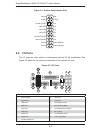
5-3 Connecting Cables
Now that the serverboard is installed, the next step is to connect the cables to the
board. These include the data cables for the peripherals and control panel and the
power cables.
1.
2.
3.
4.
5.
6.