


2
Curved
Loops
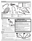
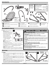
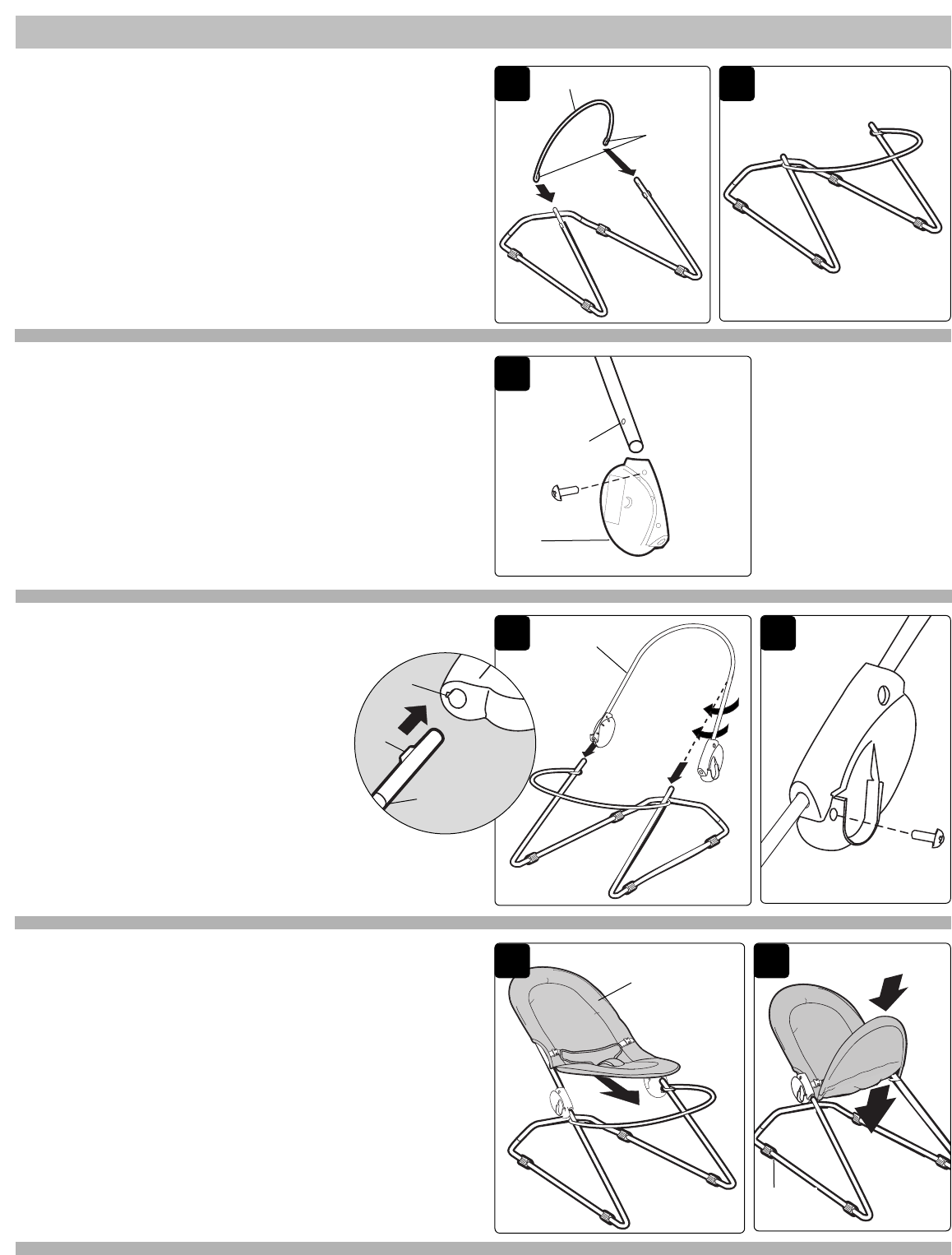
To Assemble
(continued)
Footrest Frame
PAGE 3
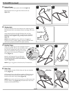
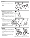
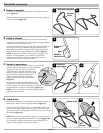
4 Headrest Frame:
Insert tab on Right Leg into slot on Right Connector
of Headrest Frame. Be sure end of headrest tube
lines up with engagement mark (line) on leg.
Rotate Headrest Frame 90 degrees and insert
Left Leg into Left Connector of Headrest
Frame (Figure 4).
Notch in Left Leg must line up with screw
hole for Locking Screw. Install and tighten
Locking Screw to fully secure frame assembly
together (Figure 4a).
NOTE: Tug on Leg joints to check security of connections.
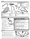
2 Footrest Frame:
Position so curved loops points downward
(Figure 2).
Slide Footrest Frame on right side and then left side
(Figure 2a).
2a
4
Headrest
Frame
4a
Tab
Slot
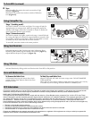
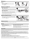
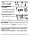
5 Fabric Seat:
Locate Pocket on back of Fabric Seat and slip over Headrest
Frame (Figure 5).
Lift Footrest Frame, and pull lower pocket of Fabric Seat over
Footrest Frame until the bottom of the Footrest meets the
bottom of the Fabric Seat pocket (Figure 5a).
NOTE: Make certain the four foot pads are in full contact with
the floor before using (Figure 5a). Reinstall Fabric Seat onto
Headrest and Footrest Frames.
5
Fabric Seat
5a
Foot
Pad
3
Screw Hole
3 Vibration Unit:
Locate the Vibration Unit and Vibration Unit Mounting Screw.
Slide Vibration Unit onto Headrest Frame and align with screw
hole.
Insert Mounting Screw through Vibration Unit and into
Headrest Frame (approximately 1/4 of the screw should be
showing)
.
Secure together using a Phillips head screwdriver
(Figure 3).
NOTE: When tightening screw, make sure it engages to
Headrest Frame. If needed, slightly reposition Vibration Unit
until screw is properly located and repeat assembly.
Vibration
Unit
Engagement
Mark