


A
B
E
H
G
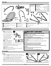
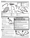
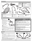
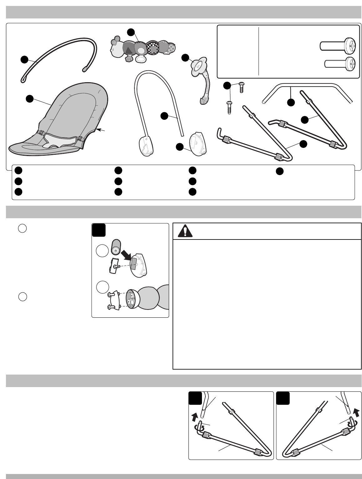
Parts List
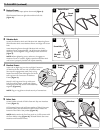
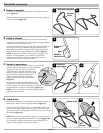
To Install Batteries
F
Curved Footrest
Fabric Seat (with restraint system)
Caterpillar Toy
Flower Toy
Curved Headrest
Vibration Unit
A
B
C
Screws (see hardware box)
Rear Leg Connector
Left Leg
G
H
I
D
E
F
C
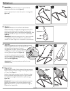
NOTE: Date
Code is
located on
back of fabric
seat.
1 Locate the vibration
unit. Use a Phillips Head
screwdriver to remove the
screw on the battery door.
Place a C-sized battery
inside. Match the (+) and
(-) symbols according to
the diagram in battery
compartment.
Locate the Caterpillar
toy. Use a Phillips Head
screwdriver to remove the
battery door. Place three
1
A
B
A
B
PAGE 2
I
Tools Needed:
Phillips Head
Screwdriver
Hardware (Quantity):
M3 x 23mm
Phillips Head
Headrest Screw, (1)
• Keep these instructions as they contain important information.
• DO NOT mix old and new batteries.
• DO NOT mix alkaline, standard (carbon zinc), or rechargeable
(nickel-cadium) batteries.
• Non rechargeable batteries are not to be recharged.
• Rechargeable batteries are to be removed from the unit before being charged.
• Rechargeable batteries are only to be charged under adult
supervision.
• Only batteries of the same or equivalent type as recommended are to
be used.
• Batteries are to be inserted with the correct polarity.
• Exhausted batteries are to be removed from the unit.
• The supply terminals are not to be short-circuited.
• Check that all contact surfaces are clean and bright before installing
batteries.
• DO NOT submerge any part of the product in water.
• Dispose of batteries safely.
• Remove batteries when stored for long periods of non-use.
BATTERY CAUTION:
AAA-sized batteries inside. Match the the (+) and (-)
symbols according to the diagram in battery
compartment.
NOTE: Batteries not included.
NOTE: Vibration Unit and Caterpillar will not operate if
batteries are installed incorrectly.
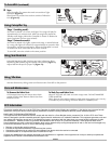
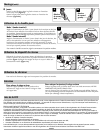
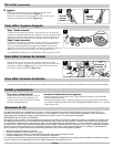
To Assemble
1 Legs:
Line up flat edge of Right Leg with dimple on Rear Leg
Connector (Figure 1). Insert leg and rotate counter clockwise.
Line up flat edge of Left Leg with dimple on Rear Leg
Connector (Figure 1a). Insert leg and rotate clockwise.
Tug on leg joints to check security of connections.
NOTE: The Legs are designed to fit firmly into the Headrest
Frame to ensure they stay in place. As a result, you may
experience some resistance when installing the Headrest Frame.
1
Rear Leg Dimple
1a
Flat Edge
Flat Edge
Rear Leg Dimple
Right Leg
Left Leg
M3 x 23mm
Phillips Head
Vibration Unit Screw, (1)
Right Leg
J
J
D