


IB-1 • 8
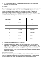
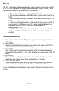
# of LEDs
R10 R11
1
470 ohms _
2
470 ohms 470 ohms
3
330 ohms 470 ohms
4
330 ohms 330 ohms
5
220 ohms 330 ohms
6
220 ohms 220 ohms
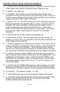
❒ 1. Install appropriate resistors R10 and R11.
❒ 2. Install infrared LEDs. Be sure that you connect them with the correct
orientation. The long lead is the anode (positive) and the short lead is the
cathode(negative). The anode is connected to either hole F or E on the PC
and the cathode is connected to hole G. You may want to use a wire to
connect the LED(s) to the PC so that they can be moved while the Interface
board itself does not.
CONGRATULATIONS
Now that you have completed your IB1 you may want to check to make sure
there are no solder bridges and that everything is in correctly. If something is
not right, be sure and make the correction before energizing the circuit.
❒ 13. Connect your camera. Follow the wiring diagram on the paperwork
enclosed with your camera.
OPTIONAL
If you are planning on using the Interface board at night or in dark areas you will
want to install R10 and R11 along with infrared LEDs. The brightness desired
can be changed by using more or less IR LEDs. The circuit is capable of
supporting up to 6 LEDs. With each LED change, R10 and R11 will also
change. Each LED connected to R10 (hole E) must be in series and each LED
connected to R11 (hole F) must also be connected in series.