


IB-1 • 4
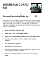
Introduction:
It is now possible to monitor what is happening at night as well as during the
daylight hours with the Interface board kit and a camera. By virtue of infrared
LEDs for night vision and a microphone attached to an amplifier circuit, you
can use it to spy on someone or as a means of added security. The Interface
board connects directly to your choice of small video cameras and has a
video and an audio output which can be plugged into a VCR or a TV (if your
TV has audio and video jacks on it ).
How It Works:
The circuit is powered by a 12 to 15 volt supply, used to operate the camera
as well as the rest of the circuit including the optional infra-red LEDs. U1 and
D1 regulate the DC supply voltage to 9 or 12 V for use in the circuit. Video is
fed directly from your camera module to the video output jack, J2.
Microphone audio is amplified by Q1 and Q2 and fed to audio output jack J3.
Test points E and F allow for connection to infra-red LEDs if so desired.
Optional R10 and R11 are current limiting resistors.
An interesting note: Because it uses state-of-the-art CCD (charge coupled
device) technology, the IB1 is extremely sensitive at low light levels, even at
infrared wavelengths. It’s possible to view the IR coming from your TV
remote control with the IB1. Also, the IB1 can be placed behind a piece of
dark Plexiglas, blocking visible light while allowing infra-red through...what an
idea for covert surveillance!
Kit building tips:
Use a good soldering technique - let your soldering iron tip gently heat the
traces to which you are soldering, heating both wires and pads
simultaneously. Apply the solder to the iron and the pad when the pad is hot
enough to melt the solder. The finished joint should look like a drop of water
on paper, somewhat soaked in.
Mount all electrical parts on the top side of the board provided. This is the
side that has no traces or pads on it.
Electrical part installation - when parts are installed, the part is placed flat to
the board, and the leads are bent on the backside of the board to prevent the
part from falling out before soldering. The part is then soldered securely to
the board; the remaining lead length is clipped off.