


Step Ten
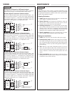
MAINTENANCE
General:
The powered level switch requires no periodic maintenance except
cleaning as required. It is the responsibility of the user to determine
the appropriate maintenance schedule, based on the specific charac-
teristics of the application liquids.
Cleaning Procedure:
1. Power: Make Sure that all power to the sensor, controller and/or
power supply is completely disconnected.
2. Sensor Removal: In all through-wall installations, make sure
that the tank is drained well below the sensor prior to removal.
Carefully, remove the sensor from the installation.
3. Cleaning the Sensor: Use a soft bristle brush and mild deter-
gent, carefully wash the powered level switch. Do not use harsh
abrasives such as steel wool or sandpaper, which might damage
the surface sensor. Do not use incompatible solvents which may
damage the sensor's PP, PFA, PVDF or Ryton plastic body.
4. Sensor Installation: Follow the appropriate steps of installa-
tion as outlined in the installation section of this manual.
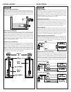
Testing the installation:
1. Power: Turn on power to the controller and/or power supply.
2. Immersing the switch: Immerse the sensing tip in its applica-
tion liquid, by filling the tank up to the switches point of actua-
tion. An alternate method of immersing the switch during prelim-
inary testing is to hold a cup filled with application liquid up to
the switch's tip.
3. Test: With the switch being fluctuated between wet and dry
states, the switch indicator light in the controller should turn on
and off. If the controller doesn't have an input indicator, use a volt-
meter or ammeter to ensure that the switch produces the correct
signal.
4. Point of actuation: Observe the point at which the rising or
falling fluid level causes the switch to change state, and adjust the
installation of the switch if necessary.
Step Nine
WIRING
Wiring as a P-Channel or N-Channel output:
The powered level switch can be substituted for either a P-Channel
(PNP, sourcing) output or a N-Channel (NPN, sinking) output.
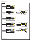
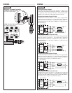
Normally Open DC Load as a P-Channel Output:
To wire as a NO P-Channel output, follow the directions below. The
Red wire connects to Positive (+) of the power supply and the Black
wire connects to Negative (-). The Green wire is jumpered to the Red
wire while the White wire is connected to the LOAD. Jumper the
LOAD back to the Negative (-) to complete the circuit.
[Dry Condition]
Sensor
(NO)
RED
GRN
SHLD
WHT
BLK
LOAD
[+]
[-]
[Dry Condition]
Sensor
(NC)
BLK
GRN
SHLD
WHT
RED
LOAD
[+]
[-]
[Dry Condition]
Sensor
(NO)
RED
GRN
SHLD
WHT
BLK
LOAD
[+]
[-]
[Dry Condition]
Sensor
(NC)
BLK
GRN
SHLD
WHT
RED
LOAD
[+]
[-]
Normally Closed DC Load as a N-Channel Output:
To wire as a NC N-Channel output, follow the directions below. The
Black wire connects to Positive (+) of the power supply and the Red
wire connects to Negative (-). The White wire is jumpered to the Red
wire while the White wire is connected to the LOAD. Jumper the
LOAD back to the Positive (+) to complete the circuit.
Normally Open DC Load as a N-Channel Output:
To wire as a NO N-Channel output, follow the directions below. The
Red wire connects to Positive (+) of the power supply and the Black
wire connects to Negative (-). The White wire is jumpered to the
Black wire while the Green wire is connected to the LOAD. Jumper
the LOAD back to the Positive (+) to complete the circuit.
Normally Closed DC Load as a P-Channel Output:
To wire as a NC P-Channel output, follow the directions below. The
Black wire connects to Positive (+) of the power supply and the Red
wire connects to Negative (-). The Green wire is jumpered to the
Black wire while the White wire is connected to the LOAD. Jumper
the LOAD back to the Negative (-) to complete the circuit.