©
National Instruments Corporation 5 SSR Series Modules and Backplanes
Caution Do not attempt to connect the SSR backplane to a host computer DAQ device for
which it was not designed. Such connections can damage any or all SSR modules,
the host computer, and the DAQ device. National Instruments is not liable for any
damages resulting from incorrect connections.
The 32-module backplane connects the PCLK1 (OUT1) and PCLK2 (OUT2)
signals of the DIO-32HS (6533) device to ground. When using a 32- module
backplane, do not configure a device for any mode that uses the PCLK1 or PCLK2
line. Specifically, do not configure the DIO-32HS (6533) for burst handshaking
mode, which uses PCLK, or write any data to port 4, which is the port that includes
the PCLK1 and PCLK2 lines. Incorrect configuration can damage the host
computer and your DAQ device. National Instruments is not liable for any
damages resulting from incorrect configuration.
Configuring the Power Supply
This section describes how to configure the SSR backplane jumpers to get
+5 VDC power to the SSR modules.
You can power the SSR module backplanes by either the DAQ device or an
external power supply. You need external power when connecting to a DAQ
device that does not supply external power or when the power needed for
the SSR modules and any other accessories exceeds the power supplied by
the DAQ device. Different DAQ devices supply different amounts of
power; for example many supply 1 A. See the specifications of your device
for more information.
The current needed for the SSR modules and accessories is the sum of the
maximum logic supply current of all SSR modules connected to the DAQ
device plus any other current needed by accessories connected to the same
DAQ device.
To configure the SSR module backplane for external power or DAQ device
power you need to set a jumper on the backplane. This can be just a wire
jumper or it can be a fuse. If you use a wire jumper, you need to fuse the
logic power supply somewhere before the backplane.
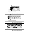
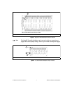
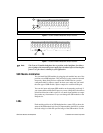
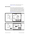
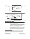
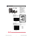
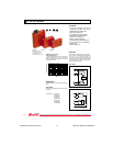
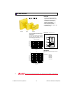
Figures 1 through 7 show the backplane power jumper locations, which are
not clearly marked on the backplane. Install only one jumper at a time. If
you install both jumpers, you can damage the supply or SSR module
backplane.
!


