SSR Series Modules and Backplanes 2
©
National Instruments Corporation
What You Need to Get Started
To set up and use the SSR Series modules and backplanes you need
the following:
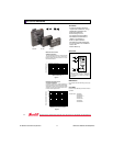
❑ SSR Series module backplane kit and documentation
❑ SSR Series module
❑ National Instruments DAQ device
❑ Cable and/or SC-205X device
❑ Number 1 and number 2 Phillips-head screwdrivers
❑ ¼ in. flat-head screwdriver
Module Operation
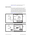
SSR modules optically isolate the field signals from the computer,
preventing any possibility of damage to the computer by overvoltage
transients on these lines. The optical isolation is rated for surges up
to 4,000 V.
Note
All SSR modules use negative logic.
Input Modules
Input SSR modules sense voltages from a field source and return a logic
value to the National Instruments DAQ device. If a voltage within the
selected input range for the input module is present, it returns a logic low
signal to the DAQ device, otherwise it returns a logic high signal.
Output Modules
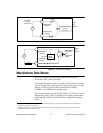
Output SSR modules sense a logic value from the DAQ device to control
external devices. They control power in a manner similar to conventional
relays. If the DAQ device sends a logic low signal, the output module turns
on and current flows. If the DAQ device sends a logic high signal, the
output module turns off.
Output SSR modules are similar to conventional relays, but there are some
important differences. Unlike conventional relays, these solid state relays
require voltage on the load side. Current needs to flow through them in the
on state, or they turn off even if a logic low signal is at their input. This
occurrence is referred to as dropout. If a solid state relay drops out, you
must turn it off with a logic high signal before you can turn it on again.


