


AR13HA/AR13HAR ROLLER (S/N 110301 & UP) • OPERATION AND PARTS MANUAL — REV. #0 (06/22/11) — PAGE 27
MAINTENANCE
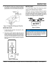
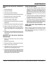
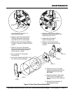
FORWARD/REVERSE RELIEF VALVES DRIVE
ADJUSTMENT
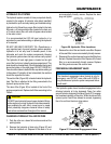
The forward and reverse relief valves (Figure 30) are
located in the hydrostatic pump (not on the manifold block)
under plugs 1 and 2 . Plug 2 is located in the same location
as plug 1, except it is on the bottom side of the pump. Relief
valve 1 is reverse and 2 is forward.
Figure 30. Adjusting Relief Valves
1. Clean the area around the cap.
2. Remove the cap.
3. Carefully remove the valve cartridge.
4. Using an allen wrench, remove the top nut (extreme
care must be taken not to loosen existing shims, spring,
or valve) Add or remove shims as required. Adding
shims increases pressure; removing shims lowers
pressure. One shim is equal to approximately 50 psi.
Shim P/N is 34538.
5. Install the top nut and install valve in the pump cavity
using extreme care not to bind.
6. Install the valve cap.
7. Retest pressure, further adjustment may be needed if
pressure is not correct.
NOTICE
Pumps supplied after 01/01/2003 do not have adjustable
relief cartridges. The pressure is fixed at 2,900 ± 145
psi. If the relief pressure is not within normal range, the
complete cartridge must be replaced.
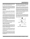
REVERSE
RELIEF VALVE
(PLUG 1)
FORWARD
RELIEF VALVE
(PLUG 2)
HYDROSTATIC
PUMP
S T E E R I N G R E L I E F VA LV E P R E S S U R E
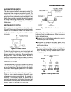
ADJUSTMENT
To adjust the relief valve steering pressure perform the
following:
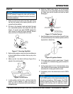
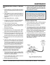
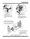
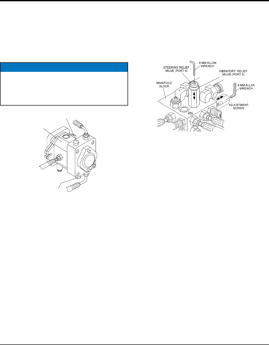
1. Insert an 8 mm allen wrench into steering relief port 4
(Figure 36) on the manifold block.
Figure 31. Steering and Vibration Relief Valves
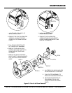
2. On the manifold, connect at 5,000 psi pressure gauge
into quick disconnect test port 1.
3. Start the engine and run at full throttle.
4. Turn the steering wheel to the left or right (maximum)
and hold. Read the steering relief pressure. The relief
pressure reading for the steering test port 1 will should
be 700 psi.
5. If the steering relief pressure is not 700 psi, using the
allen wrench adjust the pressure at port 4 until the
pressure gauge reads 500 psi.
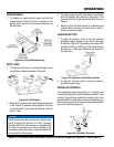
V IB R AT I ON RE L IE F VA LV E P RE S S UR E
ADJUSTMENT
1. Insert an 8 mm allen wrench into steering relief port 5
(Figure 31) on the manifold block.
2. On the manifold block, insert a 5,000 psi pressure
gauge into quick disconnect test port 1.
3. Start the engine and run at full throttle.
4. To start the vibration, press the pushbutton switch
(vibration control) located on top of the travel lever. The
relief pressure should read 900 ~ 1,500 psi.
5. If the vibration relief pressure is not 900 ~ 1,500 psi,
using the allen wrench, adjust the pressure at port 5
until the pressure gauge reads correctly.