


PAGE 22 — AR13HA/AR13HAR ROLLER (S/N 110301 & UP) • OPERATION AND PARTS MANUAL — REV. #0 (06/22/11)
OPERATION
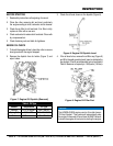
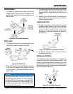
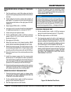
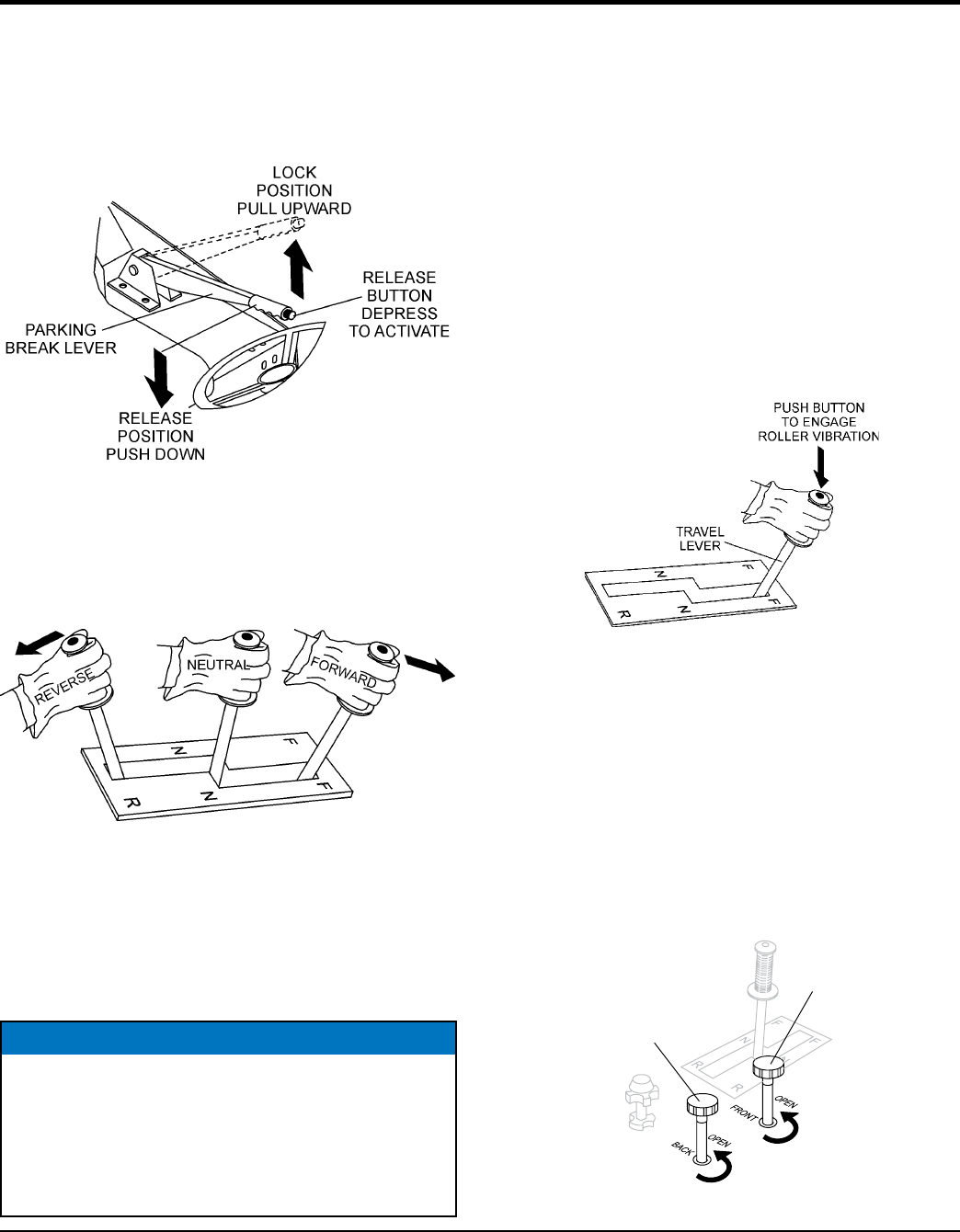
PARKING BRAKE
1. To release the parking brake, press and hold the
release button (Figure 21) pull up slightly on the
parking lever, then push the parking brake lever all
the way down.
Figure 21. Brake Release Lever
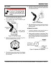
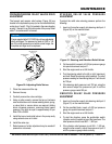
SHIFT LEVER
1. To make the roller move in a forward direction, move
the shift lever forward as shown in Figure 22.
Figure 22. Shift Lever
2. Remember the speed of the roller is directly proportional
to the amount of pressure being applied to the lever
in each direction. Travel speed is between 0 and 4.8
mph (7.2 kph).
NOTICE
ALWAYS allow the roller to come to a complete stop
before changing the direction of travel. Changing
directions before the roller comes to a complete stop
will result in excessive force being applied to the
transmission and drive system, which will reduce the
over service life of the system.
3. Try maneuvering the roller a few times to get familiar
with the handling. Also place the travel lever in the
opposite direction to get acquainted with driving in
reverse.
4. Make sure that the roller comes to a complete stop
(neutral) before placing the travel lever in either a
forward or reverse position.
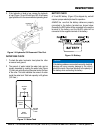
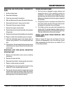
VIBRATION BUTTON
1. To begin the vibratory action, press the vibratory
pushbutton switch located on top of the travel lever
as shown in Figure 23. The pressing of this switch will
generate 3,100 lbs. (1,406 Kg.) of centrifugal force at
a frequency of 4000 vpm (vibrations per minute) to
the front drum.
Figure 23. Vibration Pushbutton Switch
2. To stop the vibratory action, press the vibratory
pushbutton switch again.
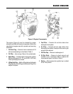
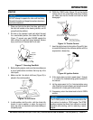
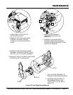
SPRINKLER CONTROLS
If the application requires the wetting of a surface, front
and rear drum sprinkler controls have been provided. These
controls (Figure 24) are located to the bottom right of the
operators seat. The front valve controls the water supply to
the front drum spray bar and the back valve controls water
flow to the back drum spray bar.
Figure 24. Sprinkler Controls
FRONT
BACK