


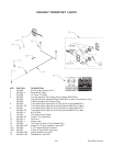


8100 Rear Unload --37--
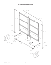
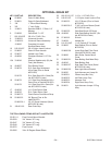
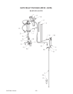
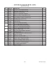
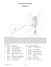
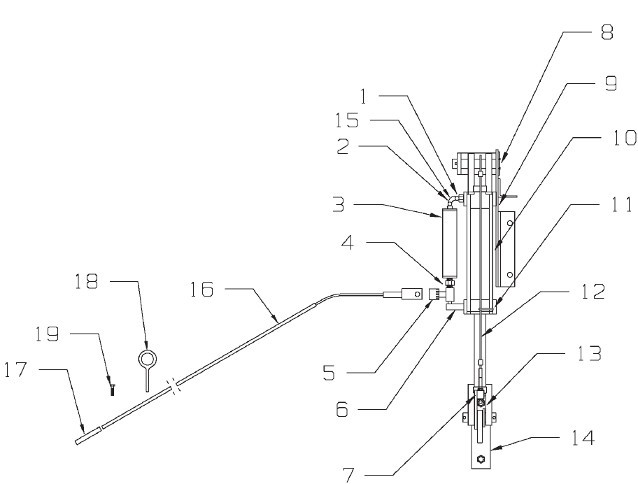
GATE DELAY PACKAGE
(#8100-Gate)
KEY PART NO. DESCRIPTION
1 55-0095 1/8" to 3/8" NPT Reducer
2 30-0015 1/4x90 Degree Elbow
3 25-8095 Oil Reservoir Assembly
4 55-0097 3/8 to 3/8" Hydraulic Nipple
5 55-0094 Flow Control Valve
6 55-0096 3/8 NPT x 90 Degree Male Pipe
Elbow
7 25-8096 Gate Release Trip Arm Assembly
8 25-8092-1 Gate Regulator Top Shaft Assy.
9 25-8090-1 Top Cylinder Bracket Assy.
10 55-0093 Hydraulic Cylinder
KEY PART NO. DESCRIPTION
11 952-0007-
1
7-1/4" Nylon Tie Strap
12 25-8098 Cable/Eyebolt Assy.
13 25-8097-1 Lower Sleeve Spacer
14 25-8093-1 Lower Shaft Plate Assy.
15 25-8095-6 Top Copper Line Assy.
16 25-8101 Ground Control Rod Assy.
W/Grip
17 51-0007 Handle Grip
18 933-3804 5/16 x 4” Eyebolt
19 825-25-1Z 1/4x1" Self Tapping Screw
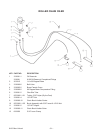
GATE DELAY ADJUSTMENTS
When thegateis completelyclosed(Tight torear upright)cableand eyeboltassembly shouldbeadjusted socable has
no slack. Cableshould betightbut notovertightened. Ifcable andeyeboltis overtightenedlowercylinder willtrip outof
the L-shapedsloton thelower brackettoo soonandthe gatewill trytoclose beforethe cylinderis strokedout. Iftheca
-
ble and eyebolt is too loose the lower cylinder will not trip out of the L-shaped slot and the cylinder will reach its maxi
-
mum stroke and the gate will still not be in the closed position. The gate will be held open by the top cylinder bracket
and the bracket may become damaged over time. Eyebolt and cable will need to be adjusted periodically to maintain
proper operation.