


SLR • SLC • SLD Slide Gate Operator Installation Guide - 5 - 227968 Revision X13 2-3-09
Operator Preparation
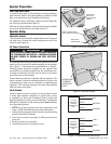
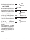
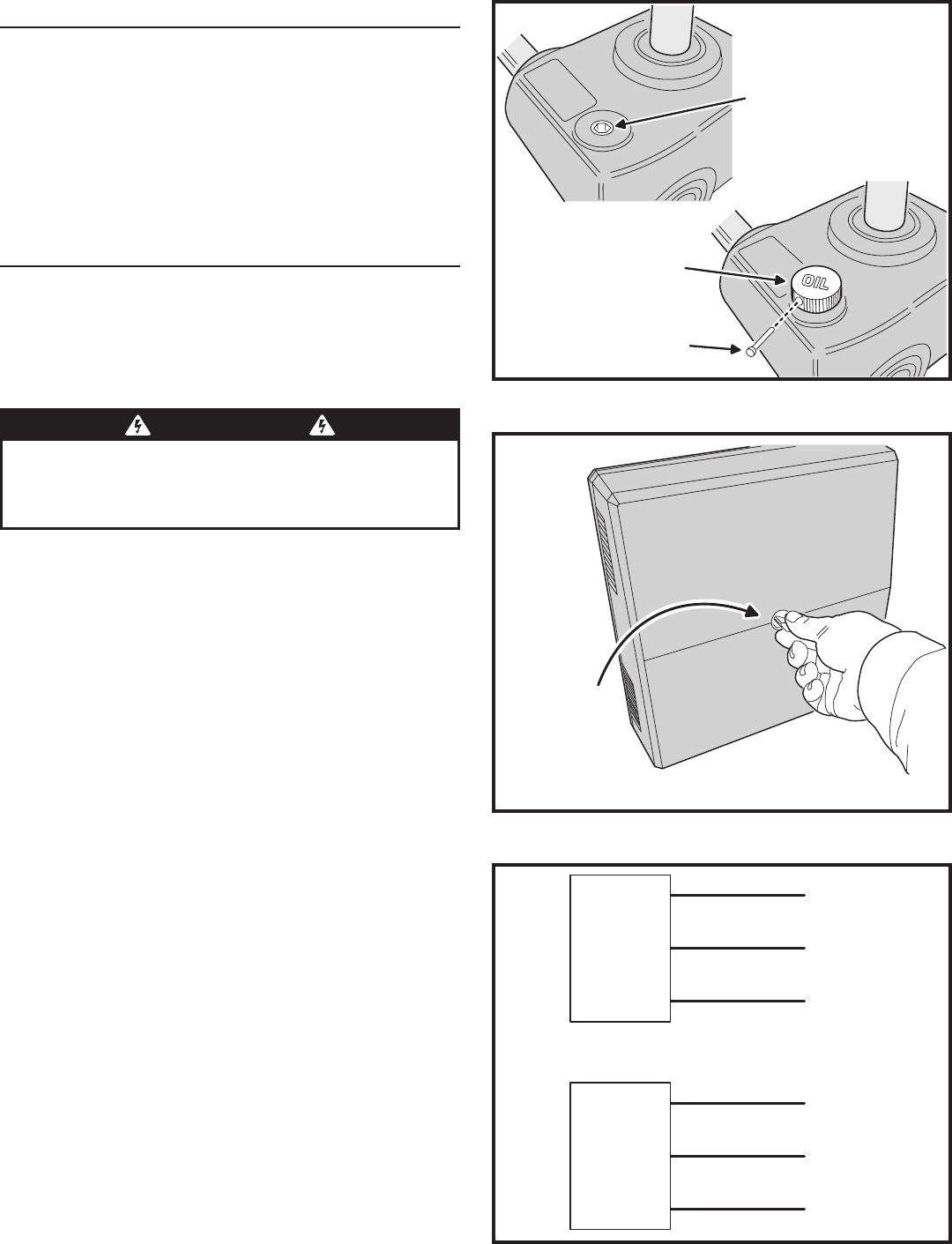
Vent Plug Installation
In order to keep gear oil from spilling out during shipping,
gear reducers used in this gate operator has either a solid
plug, or a sealed vent plug, installed at the factory.
For operators with a solid plug, replace the solid plug with
the vent plug provided (see Figure 5).
With the vent plug installed, remove the vent plug’s breather
pin to allow the gear box to vent (see Figure 5).
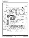
Operator Setup
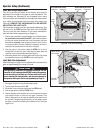
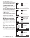
Controller Access
The Controller is protected by a plastic dust cover. To remove
the dust cover, loosen the cover’s wing-screw and lift the
cover off (see Figure 6).
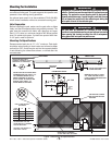
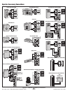
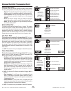
AC Power Connection
All Linear gate operators are supplied with a power disconnect
switch to turn on and off the power available to the operator
(see Figure 7). Following wiring specifications on Page 2,
incoming power should be brought into the operator and
connected to the labeled pigtails from the disconnect box.
A wiring connections print can also be found on the label
inside the cover of the operator.
Proper thermal protection is supplied with the operator. The
motor contains a thermal overload protector to guard from
overheating the motor due to overload or high-frequency
operation. This overload protector will reset automatically
after the motor cools down.
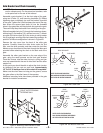
Earth Ground
Install a ground rod and connect it to the operator’s frame
in every gate operator installation. A good earth ground
is necessary to allow the Controller’s built-in surge and
lightning protection circuitry to work effectively. The physical
bolting of the operator to the mounting pad is not sufficient
for a good earth ground.
✓ NOTE: Do not splice the ground wire. Use a single piece of solid
copper 12 AWG wire between the ground rod and the operator.
1. Install an 8-foot long copper ground rod next to the operator mounting
pad within three feet of the operator.
2. Use a clamp to connect a solid copper 12 AWG ground wire to the
ground rod.
3. Route the ground wire to the operator.
4. Connect the ground wire to the operator’s frame.
Figure 7. Power Disconnect Box Wiring
110 VOLT
OPERATOR
POWER
DISCONNECT
BOX
BLACK
220 VOLT
OPERATOR
POWER
DISCONNECT
BOX
WHITE
GREEN
BLACK
BLACK
GREEN
HOT
NEUTRAL
GROUND
LINE 1
LINE 2
GROUND
Figure 5. Vent Plug Installation
REMOVE THE
SOLID PLUG
WITH AN ALLEN
WRENCH
INSTALL THE VENT PLUG
(IF NOT ALREADY INSTALLED)
REMOVE THE
BREATHER PIN
GEAR
REDUCER
Figure 6. Controller Access
LOOSEN KNOB
TO REMOVE
CONTROLLER
COVER
WARNING
ALL AC ELECTRICAL CONNECTIONS TO THE POWER SOURCE AND
THE OPERATOR MUST BE MADE BY A LICENSED ELECTRICIAN
AND MUST OBSERVE ALL NATIONAL AND LOCAL ELECTRICAL
CODES