


SLR • SLC • SLD Slide Gate Operator Installation Guide - 11 - 227968 Revision X13 2-3-09
Basic Controller Programming
Programming Overview
The Controller can be programmed with various options for the operator.
The programming fields are defined as “functions” that have “options”. To
make setup easier for the installer, the Controller’s programming is divided
into two groups: basic and advanced. The basic programming group
contains the functions commonly used in most slide gate installations.
The advanced programming group contains functions less commonly
used (i.e. dual gate stagger delay, maximum run timer, etc.).
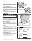
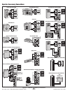
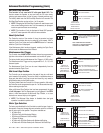
Entering Programming Mode
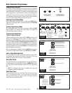
Enter programming mode by pressing the UP and DOWN buttons
together for one second. While in programming mode the PROGRAM
indicator will light.
Exiting Programming Mode
Exit programming mode at any time by pressing the UP and DOWN
buttons together. The Controller will automatically exit programming
mode after three minutes of inactivity.
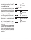
Programming Keystrokes
(Typical Programming Method)
While in programming mode, press the UP or DOWN buttons to scroll
through the programming functions. When the desired function is
displayed press the ENTER button to display the currently set option for
the function. When an option is displayed, the decimal points are lit.
To change the option, press and hold the ENTER button for 1 second. To
indicate that an option is ready to be changed, the display will flash. While
the display is flashing, press the UP or DOWN button to display the other
options available for that function.
When the desired option is displayed, press the ENTER button to store it
into memory. To select another function, press ENTER, UP, or DOWN.
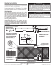
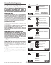
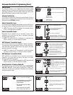
Left or Right Hand Operation
The factory default is for right hand operation (operator on right side of
the driveway when viewed from the inside of the gate). For left hand
installations, program the Controller for left hand operation.
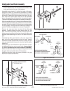
Dual Gate Enable
The factory default is for single gate operation. For dual gate operation,
wire the two gate controllers together through the COMM LINK terminals
(see Page 23) and enable dual gate operation with this programming
step.
✓ NOTE: The Mid-travel Stop feature is disabled when dual gate
operation is enabled for paired units.
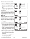
Auto Close Timer
The factory default turns off the Auto Close Timer. The timer can be set
from 1 to 59 seconds and from 1 to 9 minutes. When the Auto Close
Timer is set, after opening, the gate will wait for the length of the Auto
Close Timer then close automatically.
PRESS DOWN AND UP
BUTTONS TOGETHER
FOR ONE SECOND
PROGRAM INDICATOR
WILL LIGHT WHEN SYSTEM
IS IN PROGRAM MODE
PROGRAM
INDICATOR
AND
DOWN UP
ENTERING
PROGRAMMING
FUNCTION
LEFT HAND INSTALLATION
(OPERATOR ON LEFT OF GATE
WHEN VIEWED FROM INSIDE)
RIGHT HAND INSTALLATION
(OPERATOR ON RIGHT OF GATE
WHEN VIEWED FROM INSIDE)
OPTIONS
PRESS UP OR
DOWN TO CYCLE
THROUGH OPTIONS
PRESS ENTER TO
SELECT AN OPTION
LEFT HAND
RIGHT HAND
"RL"
PRESS UP OR DOWN
TO SCROLL DISPLAY
THROUGH FUNCTIONS
PRESS ENTER FOR
ONE SECOND TO
SELECT OPTION
(THE DISPLAY
WILL FLASH)
PRESS UP
OR DOWN
TO CHANGE
OPTION
ENTER
PROGRAMMING
KEYSTROKES
SELECT
FUNCTION
CURRENTLY
SET OPTION
OPTION READY
TO CHANGE
PRESS ENTER TO
DISPLAY CURRENTLY
SET OPTION
CHOOSE
OPTION
OR
UP
DOWN
OR
UP
DOWN
OPTION
STORED
PRESS ENTER
TO STORE
OPTION
SELECT
FUNCTION
ENTER ENTER ENTER
OR
UP
DOWN
OR
PRESS UP, DOWN
OR ENTER SELECT
NEXT FUNCTION
FUNCTION
DUAL GATE INSTALLATION
SINGLE GATE INSTALLATION
OPTIONS
PRESS UP OR
DOWN TO CYCLE
THROUGH OPTIONS
PRESS ENTER TO
SELECT AN OPTION
SINGLE GATE
DUAL GATE
"PM"
FUNCTION
SET TIMER VALUE
1 TO 59 SECONDS
AUTO CLOSE TIMER DISABLED
SET TIMER VALUE
1 TO 9 MINUTES
OPTIONS
PRESS UP OR
DOWN TO CYCLE
THROUGH OPTIONS
PRESS ENTER TO
SELECT AN OPTION
AUTO CLOSE
TIMER
"AC"