


MODEL BGUS/BGUS-D • SG/SG-D OPERATOR INSTALLATION GUIDE
-9-
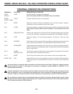
Auto Close Timer Adjustment: This 270-degree adjustable potentiometer will signal the operator to close automatically, from the fully
open position, provided no open, reversing or obstruction signals are present. The timer is adjustable from 0 to 124 seconds. This feature
is turned off or on using dip switch #1.
Maximum Run Timer Adjustment: This 270-degree adjustable potentiometer should be left in the fully clockwise position on all barrier
gate operators.
Open Direction Current Sense Adjustment: This multi-turn potentiometer is used to calibrate the built-in current sensing feature for
detection of obstructions while running in the open direction.
Close Direction Current Sense Adjustment: This multi-turn potentiometer is used to calibrate the built in current sensing feature for
detection of obstructions while running in the closed direction.
Master/Slave Connection Block: This terminal block is used in conjunction with two operators to confi gure two gates to open and close
together.
Dip Switches:
#1 This switch turns the auto close timer off/on.
#2 This switch controls the behavior of the open/reset function in barrier gates only. When the switch is turned ON, a momentary open/
reset pulse will cause the arm to raise and stay raised until a reset or another open/reset signal occures. In the ON position, this
switch also disables the counting function of Dip Switch #4. When the switch is turned OFF, the arm will lower as the open/reset
signal is no longer present.
#3 This switch is used in conjunction with single-button controls and radio receivers. In the ON position, successive inputs will cause
signals in the order of OPEN-STOP-CLOSE-STOP. In the OFF position, inputs will cause an OPEN signal unless the gate is fully
open, in which case it will signal CLOSE.
#4 In the OFF position, for every open signal the barrier gate receives, there must be a reset signal before the arm will come down. In
the ON position, this feature is disabled.
#5 In the OFF position, if two vehicles are close together and the second vehicle triggers the reset loop as the arm is coming down, the
arm will stop until the second car is clear of the loop, then continue down. In the On position, the arm will continue down even when
a second car triggers the reset loop. If the application requires that only a single vehicle pass through at a time, then this featurte
should be ON. In all other cases the feature should be left OFF, as the arm will come down onto a tailgating vehicle.
#6 In the ON position, this switch will disable the inherent DC brake in DC operators only. In addition, the R2 brake resistor on the DC
motor board must be cut from the board (refer to the picture above). In the OFF position, the DC brake will function.
#7 Not used at this time.
#8 This switch is used to set Master/Slave confi guration. Operators which are stand-alone or master units should be set to OFF, while
only slave units should have this switch set to ON.
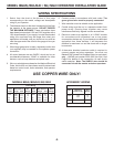
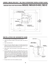
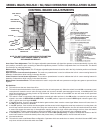
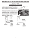
CONTROL BOARD ADJUSTMENTS
NOTE: DO NOT FORCE 270-DEGREE POTENTIOMETERS
BEYOND THEIR NORMAL RANGE OF MOTION
OR DAMAGE MAY RESULT!
Control Board
with DC
Motor Board
DIAGNOSTIC
L.E.D.s
TERMINAL STRIP #2
CONNECTOR
TERMINAL STRIP #1
CONNECTOR
LIMIT SWITCH
CONNECTOR
LIMIT SWITCH
L.E.D.s
3A FUSE
2A FUSE
R2 BRAKE
RESISTOR