


MODEL BGUS/BGUS-D • SG/SG-D OPERATOR INSTALLATION GUIDE
-21-
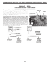
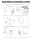
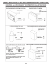
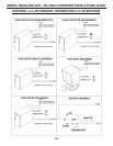
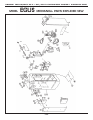
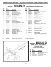
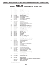
MODEL BGUS-D MECHANICAL PARTS LIST
Ref. Part
No. Number Description
2 2110-781* Welded Cabinet Assembly
3 2100-372* Enclosure Door
5 2220-008 Lock Assembly with Key
6 2110-746 Bearing Block Assembly Kit
7 2110-170 Drive Shaft Assembly
8 2110-732 Gate Arm Flange
9 2100-1925-BT Arm Attachment Channel
10 2100-1926-BT Counterweight
12 2110-441 Connecting Link with Bearings
26 2200-136 Flange Bearings
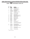
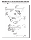
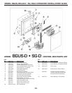
17 2500-1902 Motor 24 VDC
2510-243 Brush Replacement Kit
2110-834 Motor Mounting Bracket (not shown)
18 2100-364 Intermediate Shaft
19 2110-117 Reducer and Crank Arm assembly
21 2200-917 Reducer Pulley, 7” (2 required)
22 2200-918 Intermediate Pulley, 2” (2 required)
23 2200-1003 V-Belt, cogged, 25” (2 required)
24 2200-235 Motor Pulley, 1 5/8”
25 2200-011 Intermediate Pulley, 6”
28 2200-208 V-Belt, 26” (2 required)
29 2400-178 Carriage Bolt, 3/8”-16 x 1 1/2”
30 2400-015 Hex Nut, 3/8” -16
31 2400-017 Flat Washer, 3/8”
32 2400-182 Wing Nut, #10-32
33 2200-314 Set Collar, 1 1/4”
34 2400-474 Roll Pin, 3/8” x 1” x 2”
35 2400-043 Star Washer, #10
36 2400-032 Hex Nut, #10-32
37 2400-049 Screw, #8 - 32 x 3/8”, self-tap
38 2500-029 Limit Switch
40 2400-246 Screw, #6 - 32 x 2 1/4”, Pan-Head
42 2400-069 Keps Nut, #6-32
43 2300-028 Limit Cam
50 2400-238 Key, 3/16” x 3/16” x 1 1/4”
51 2400-254 Key, Intermediate Shaft
55 2400-188 Thrust Washer
56 2400-165 Shoulder Bolt, 1/2” - 32 x 2”
60 2200-222 Bearing, Pillow Block
61 2400-133 Key, Intermediate Shaft
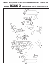
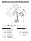
71 2510-223 Transformer Assembly
2500-1768 Bridge Rectifi er
2500-1769 Diode
2500-1776 Transformer only, 115/24V, 250VA
2500-1819 Fuse Holder
2500-1742 Fuse, 6A Slow-Blow
72 2100-1879 Power Box Mounting Plate
73 2510-266 Power On/Off Switch Assembly
2500-726 Switch only (20 Amp)
74 2100-1820 Front Accessory Shelf
76 2500-182 Battery Assembly
(LINEAR supplied - some distributors
supply other batteries)
2500-1118 Battery, 12V (2 required)
2300-450 Velcro Tape, per foot
*Specify color and texture.
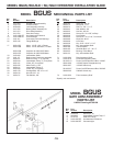
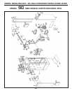
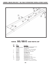
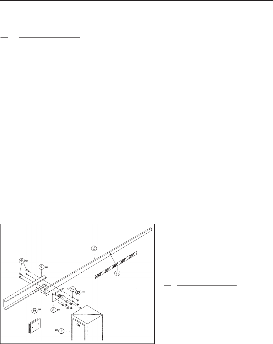
MODEL BGUS-D
GATE ARM ASSEMBLY
PARTS LIST
LINEAR Drawing #2700-084
Ref. Part
No. Number Description
2 2120-330 Wood Arm, 16’
6 2300-663 Yellow/Black Caution Tape, 2”
8 2110-732 Gate Arm Flange
9 2100-1925-BT Arm Attachment Channel
10 2100-1926-BT Counterweight
Ref. Part
No. Number Description