


MODEL BGUS/BGUS-D • SG/SG-D OPERATOR INSTALLATION GUIDE
-10-
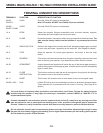
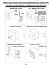
TERMINAL CONNECTION DESCRIPTIONS
TERMINALS FUNCTION DESCRIPTION OF FUNCTION
24VAC 24VAC Provides 24Volt AC power for accessories.
24VAC N Note: DC models will NOT have 24Volt AC power available.
24VDC+ 24VDC Provides 24Volt DC power for accessories.
24VDC- COMM.
1 & 4 OPEN Opens the operator. Several accessories such as button stations, keypads,
transmitters and card readers can be wired to open.
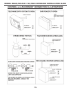
3 & 4 CLOSE Closes the operator. Use caution when wiring accessories to these terminals. The
gate must be clearly visible from the location of any accessories wired to
close.
4 & 5 SINGLE-BUTTON Performs the single-button function which will alternate between open and close
or open, stop and close - depending on dip switch #3. (See Page 9 for details.)
2 & 4 STOP Stops the operator. On barrier gate operators, this button is also the reset
button.
4 & 6 REVERSE This function will cause a reversal when the gate is traveling closed and will travel
back to the fully open position. Loop detectors are often wired for reverse.
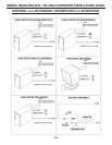
4 & 50 OPEN/RESET A signal across these terminals will cause the arm of the barrier gate operator to
raise and stay open until the signal is gone, at which point the arm will immediately
begin to come down.
4 & 51 CLOSE This function works only while the arm is coming down. Any signal to this function
will cause the arm to stop and fully reverse.
4 & 11 RESET This function will cause the arm to come down as soon as the signal clears.
24VDC+ & 60 RUN A 24Volt DC device such as a strobe light or alarm can be wired to these terminals.
These devices will be powered while the motor is running. (See Page 9 for
details.)
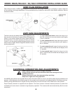
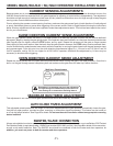
OBSTRUCTION
You must follow all required safety precautions and instructions at all times. Review the safety brochure
included with the operator. If any pages are missing or unreadable, contact LINEAR at 1-800-333-1717 to
request additional copies.
Do not adjust the circuit board current sensing feature too high. It should be adjusted high enough to keep
the gate arm from falsely triggering the sensing, but no higher than necessary for the barrier gate to operate.
Do not defeat the purpose of this function!
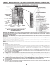
Controls intended for user activation must be located at least six feet (6’) away from any moving part of the
gate and where the user is prevented from reaching over, under, around or through the gate to operate the
controls. Outdoor or easily accessible controls shall have a security feature to prevent unauthorized use.