


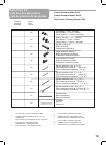

For further clarification, please see back of user
guide for corresponding drawings.
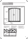
1. The gate must be installed in a structurally sound
opening. Never install between two railings or two stair
posts.
Ensure mounting surface (wall, doorframe, stair post,
etc.) is strong, rigid and is smooth, clean and grease
free.
If mounting onto brick, drywall or other surfaces,
an optional gate installation kit, wooden board
mounted to the surface or additional hardware may
be necessary to provide a solid, smooth surface.
Measure opening to determine if extensions are
needed. Correct width will be reached by adjusting all
4 corner spindles. Each spindle adjusts individually
and may be extended to varying lengths (up to 1¾”
each) to allow for molding, uneven walls, etc.
If using gate on a stairway, it must be placed on the
lowest stair on bottom.
2. Spindle attachment is different when using
extensions and when not using extensions.
If no extension/s are used, slide top spindles (b) and
bottom spindles (s) into spindle housing end with out
tab (c). Push assembly into gate corners.
3. If using extension/s, (see Extension Placement
Guide) insert square extension tubes (j) into gate ends.
Connect the bar (k) to one upper extension housing (h)
and one lower extension housing (i). Push assembly
over extension tubes.
There should be no metal showing from extension
tubes. It may be necessary to apply pressure to tubes
to ensure they are fully inserted into gate ends. Slide
top spindles (b) and bottom spindles (s) into extension
tubes.
4. Note:
Spindle housings are not used if square extension
tubes are necessary. If the housings have been
inserted, remove with a screwdriver.
5. Center the gate in opening with bottom rail resting
on floor. Gaps on each side should be equal.
Open the handle to the raised position by pressing the
buttons (r) and lifting the handle (n) at the same time.
BUTTONS MUST ALWAYS BE PRESSED IN WHEN
LIFTING HANDLE.
FAILURE TO DO SO WILL RESULT IN HANDLE
MECHANISM BREAKING.
Installation
5
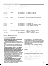
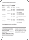
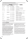
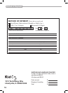
Extension Placement Guide
Extension Placement Guide for Premier Gateway Model G150
Note: Each G5.5 Kit contains two extensions Note: Each G12.5 Kit contains one extension
Width Opening Extensions What You Need Placement
29” – 31 ½” Basic Gate No extensions
31 ½” - 34 ½” Included with Gate Gate + 1 extension -on one end
34 ½” – 37” Gate + 2 extensions -1 on each end
37” – 40” 1 G5.5 Kit Gate + 3 extensions -2 on one end; 1 on other end
40” – 42 ½” Gate + 4 extensions -3 on one end; 1 on other end
42 ½” – 45” 2 G5.5 Kits Gate + 5 extensions -3 on one end; 2 on other end
45” – 47 ½” Gate + 6 extensions -3 on each end
47 ½” – 49 ½” 1 G12.5 Gate + 3 extensions -G12.5 on either end; 1 extension on each end
49 ½” – 52” 1 G12.5 + 1 G5.5 Kit Gate + 4 extensions - 1 G12.5 + 2 extensions on one end;
1 extension on other end
52” – 55” Gate + 5 extensions - 1 G12.5 + 2 extensions on one end;
2 extensions on other end
55” – 57” 2 G12.5 Gate + 2 extensions -1 G12.5 on each end
57” – 60” Gate + 3 extensions -1 G12.5 on each end; 1 extension on one end
60” – 62” Gate + 4 extensions -1 G12.5 + 1 extension on each end
62” – 65” 2 G12.5 + 1 G5.5 Kit Gate + 5 extensions - 1 G12.5 + 1 extension on each end;
1 exten
sion on one end
65” – 68” Gate + 6 extensions -1 G12.5 + 2 extensions on each end
68” – 70” 2 G12.5 + 2 G5.5 Kits Gate + 7 extensions -
1 G12.5 + 2 extensions on each end;
1 extension on other end
70” – 73 ½” Gate + 8 extensions -1 G12.5 + 3 extensions on each end
Each end may have no more than 4 extensions.
Extensions must be added as shown.