


4 Intel NetStructure
®
MPRTM0020 Technical Product Specification – April 2006
6.4.1 Mean Time Between Failure (MTBF) Specifications .............................................35
6.4.1.1 Environmental Assumptions ..................................................................35
6.4.1.2 General Assumptions............................................................................. 35
6.4.1.3 General Notes........................................................................................36
6.5 Power Consumption ...........................................................................................................36
7 Warranty Information .................................................................................................................. 37
7.1 Intel NetStructure
®
Compute Boards and Platform Products Limited Warranty.................37
7.2 Returning a Defective Product (RMA) ................................................................................37
7.2.1 For the Americas ................................................................................................... 37
7.2.2 For Europe, Middle East, and Africa (EMEA) ........................................................38
7.2.3 For Asia and Pacific (APAC)..................................................................................38
7.2.4 Limitation of Liability and Remedies ...................................................................... 39
8 Customer Support.......................................................................................................................40
8.1 Customer Support...............................................................................................................40
8.2 Technical Support and Return for Service Assistance .......................................................40
8.3 Sales Assistance ................................................................................................................40
8.4 Product Code Summary .....................................................................................................40
9 Certifications................................................................................................................................41
10 Agency Information..................................................................................................................... 42
10.1 North America (FCC Class A).............................................................................................42
10.2 Canada – Industry Canada (ICES-003 Class A) ................................................................42
10.3 European Union.................................................................................................................. 42
11 Safety Warnings ..........................................................................................................................44
11.1 Safety Precautions..............................................................................................................44
Figures
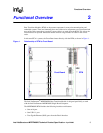
1 Relationship of RTM to Front Board .............................................................................................9
2 Default Grounding on MPRTM0020 ...........................................................................................12
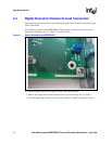
3 Digital Ground Connected to Chassis Ground ...........................................................................13
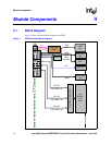
4 RTM Functional Block Diagram..................................................................................................14
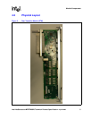
5 Rear Transition Module (RTM) ...................................................................................................15
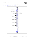
6 RTM Faceplate Connectors and LEDs.......................................................................................16
7 Serial Port Connector ................................................................................................................. 17
8 USB Connector (J2) ...................................................................................................................18
9 RJ-45 Gigabit Ethernet Connector .............................................................................................19
10 SAS Connector........................................................................................................................... 20
11 RJ-48 Connector ........................................................................................................................ 21
12 P30 Connector............................................................................................................................22
13 RTM Power Distribution.............................................................................................................. 26
14 Physical Breakdown of SAS Ports Distribution........................................................................... 27
15 RJ-45 Ethernet Port LEDs ..........................................................................................................28
16 RTM Temperature Sensor Locations ......................................................................................... 32
17 Component Layout .....................................................................................................................34