Intel NetStructure
®
MPRTM0020 Technical Product Specification – April 2006 35
Detailed Specifications
6.4 Reliability Specifications
6.4.1 Mean Time Between Failure (MTBF) Specifications
Calculation Type: MTBF/FIT Rate
Standard: Telcordia* Standard SR-332 Issue 1
Methods: Method I, Case I, Quality Level II
The calculation results were generated using the references and assumptions listed. This report and
its associated calculations supersede all other released mean time between failures (MTBF) and
Failure in Time (FIT) calculations of earlier report dates. The reported failure rates do not represent
catastrophic failure. Catastrophic failure rates will vary based on application environment and
features critical to the intended function.
6.4.1.1 Environmental Assumptions
•
Failure rates are based on a 40° C ambient temperature.
• Applied component stress levels are 50% (voltage, current, and/or power).
• Ground, fixed, controlled environment with an environmental adjustment factor equal to 1.0.
6.4.1.2 General Assumptions
• Component failure rates are constant.
• Board-to-system interconnects included within estimates.
• Non-electrical components (screws, mechanical latches, labels, covers, etc.) are not included
within estimations.
• Printed circuit board is considered to have a 0 FIT rate.
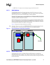
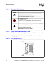
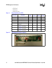
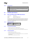
Table 17. Board Components
Component/Function
A SAS Retimer
B
RMD/ENA jumper. Used to bypass the manageability by the MPCBL0020 SBC IPMC for debugging
purposes. Not intended to be use in any field deployment, because changing this default jumper affects
the RTM manageability from the ShMC.
C ADM1026
D Digital/Chassis Ground Jumper
Table 18. Reliability Estimate Data
Failure Rate (FIT) 913 failures in 10
9
hours
MTBF 1,095,000 hours


