


5
134-10-99 IS2478
678
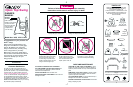
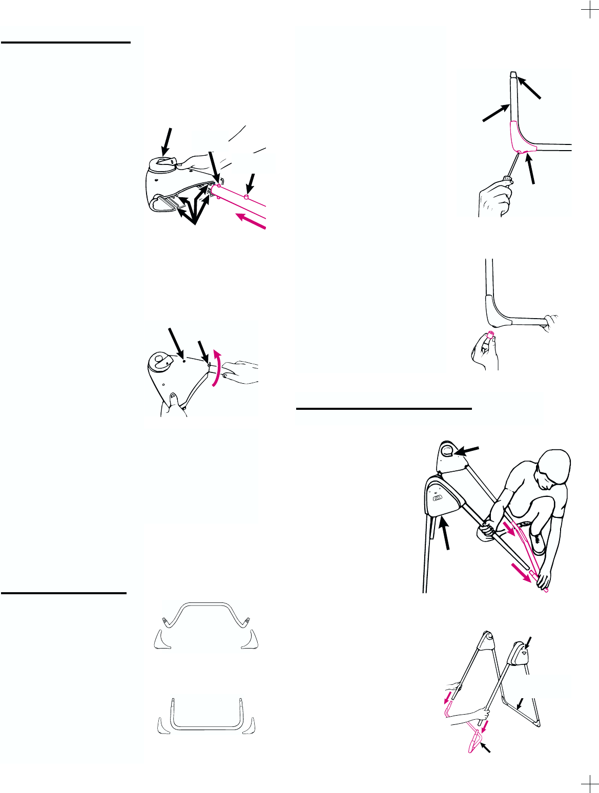
Attaching the Legs
Step 1.
The four legs have a double
button at one end and a
single button beneath it.
With the hub sides facing up,
place the motor housing and
pivot housing on the floor.
Position legs so their single
buttons also face up.
Insert legs into the motor
housing and pivot housing as
shown. The double buttons
must fit into the channels
inside the housings.
Step 2.
Push each leg in until the
double button snaps into the
hole at the end of the channel.
Then swing the legs outward
until the single button snaps
into its notch, as shown.
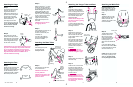
Attaching the Feet
Step 1.
Identify the front and rear base
tubes from pictures at right.
The feet to use with each tube
can be identified by the text
FRONT BOTTOM or REAR
BOTTOM printed on them.
Step 2.
Begin by inserting a 1
1
/8" screw
all the way into the small hole
on one foot. Position the foot as
shown at right, so the text and
viewing hole are not on the
short side of tube near the
wire end. Then use viewing hole
to line up the end of the screw
with the hole in the tube.
Tighten the screw securely.
Repeat above steps for the
other feet.
CHECK that feet are secure
by wiggling the feet.
Step 3.
Push a plastic tip onto all four of
the feet. Tap leg tips on
the floor to be sure they are
completely on.
The hole in the plastic tip
permits future tightening of
the screw if needed.
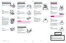
DO NOT separate the two
parts of the buckle. This will
make it easier to thread the
belt through the buckle cor-
rectly.
Step 1.
Thread the free end of the
waist belt through the belt
retainer as shown. The
GRACO logo will be on the
front of the buckle.
Step 2.
Thread belt through the
buckle as shown. The
left end of the buckle
must be smooth side up
to thread the belt in the
buckle properly. The
other side of the buckle has
teeth.
If you have difficulty getting
the belt into the buckle, check
to make sure that the smooth
side of the buckle is up.
CHECK that the belt is thread-
ed correctly by pulling on the
waist belt. The belt should
not slip through the buckle.
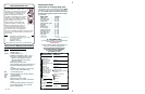
Step 1.
From rear of swing, depress
metal button and push short
end of one hanger tube into one
hanger bracket as shown. When
the metal button pops out, the
tube is locked. Repeat with
other hanger tube.
CHECK that the hanger tubes
are secure in hubs by pulling
firmly on them.
To remove hanger tubes from
hubs, push metal buttons in and
pull hanger tubes out.
Step 2.
Slide seat onto the hanger
tubes. Line up the holes in the
seat armrests with the holes
in the straight sections of the
hanger tubes.
Put a machine screw through
the holes, with head of screw
on inside of the seat. Secure
screw with an acorn nut, and
tighten it securely with the
enclosed wrench. Repeat on
other side.
The seat
back must overlap armrests,
as shown enlarged at right.
Step 3.
Slide the seat wire through the
seat back loops.
Step 4.
Insert the end of the seat wire
through the hanger tubes as
shown. Then screw acorn nuts
on both ends of the seat wire
and tighten securely with the
enclosed wrench.
Do not use
swing if the seat wire is not
securely attached. If seat can
recline backwards between
the hanger tubes, check the
wire assembly.
Double
button
Single
button
PUSHChannels
Hub
Button
in hole
Notch
CHECK that the legs are properly attached by twist-
ing them in the housings. They should resist twist-
ing. If a leg twists and buttons come out of their
holes, insert leg into the housing again. Be sure to
align BOTH double buttons with BOTH sets of
channels inside the housings.
Front base
tube
Front
foot
Rear
foot
Rear base
tube
Text and
viewing hole
Wire
end
Short side
of tube
Button
in slot
Acorn nut on
outside of seat
Attaching the Hanger Tubes and Seat Attaching the Waist Belt
Attaching the Base Tubes
Step 1.
Push the legs firmly onto
the rear base tube
exactly as shown.
Step 2.
Push the other two legs onto
the front base tube.
CHECK that all tubes are
securely attached.
CHECK that the parts of the
frame are assembled in the
positions shown.
Motor
housing
(switch
side)
PUSH
Straight rear
base tube
Bent front base tube
PUSH
Switch
side of
motor
housing
Bracket hole
points toward
rear of swing
Smooth side