


22
•
TRAXXAS
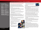
TUNING ADJUSTMENTS
MOTOR AND GEARING
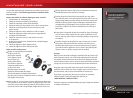
Extensive testing has been done to determine the best gear ratio
for your model. The stock gearing balances power, speed, and
efficiency to optimize the performance of the model. However,
you may wish to try different gear ratios in order to customize the
performance of your model. The gearing chart on this page shows
appropriate gearing for the model.
By installing a pinion with fewer teeth, or a spur gear with
more teeth, the transmission’s final drive ratio is increased.
This means greater rpm is required to achieve a given speed.
Using a numerically higher gear ratio will increase torque, but
reduce top speed. Installing a pinion with more teeth, or a spur
gear with fewer teeth, will decrease the final drive ratio, which
will generally increase top speed but reduce torque. However,
installing too large a pinion will “overgear” the model, which will
reduce performance and may overheat the motor and speed
control. Use the following formula to calculate the overall ratio for
combinations not listed on the gear chart:
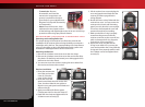
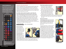
Motor Installation
To access the motor,
remove the gear cover
by removing the single
screw on the top of the
gear cover. The motor
uses an aluminum
mount for quick, easy
motor access and
gearing adjustment. To
remove the motor, first
open the right battery
door and slide out the ESC. Next, remove the single large hex screw
using the supplied 2.5mm wrench. Then rotate the motor and
mount to the side of the model, and slide backward off the post.
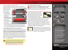
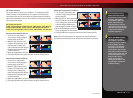
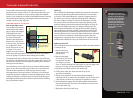
Pinion Gear Installation Instructions
1. Remove the motor as described
previously in Motor Installation.
2. Use a 1.5mm wrench to loosen the
pinion’s set screw. Remove the pinion.
3. Place the replacement pinion gear onto
the motor shaft. Align the set screw
hole with the flat side of the shaft.
4. Thread a 1.5mm set screw into the
pinion gear but do not tighten it yet.
5. Slide the pinion gear down the motor shaft so the wrench shaft
fits into the notch in the motor mount, as shown. Tighten the
set screw.
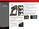
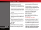
Adjusting Gear Mesh
Incorrect gear mesh is the most common
cause of stripped spur gears. Gear mesh
should be checked and adjusted anytime
a gear is replaced. Access the gears by
removing the single screw on the top
gear cover.
To set the gear mesh, cut a narrow strip of
notebook paper and run it into the gear
mesh of the motor. The motor is mounted
to an aluminum motor mount. Loosen
the single motor mount screw with the
provided 2.5mm wrench to slide the motor
mount. Slide the motor and pinion gear into
the spur gear. Retighten the motor mount
screw and then remove the strip of paper.
You should be able to run a fresh strip of
paper through the gears without binding
them. Gear mesh can be checked visually by
removing the gear viewing port cover.
Motor Mount
Screw
Do Not Loosen
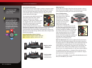
# Spur Gear Teeth
x 5.04 = Final Gear Ratio
# Pinion Gear Teeth
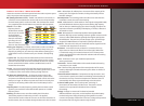
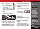
Gearing Compatibility Chart
The chart on the left shows a full range of
gear combinations. The stock ratio for is
shown in green. The gear combinations
in red are not suitable when using the
included 6-cell battery, speed control
and motor. These gear combinations
have been included in this chart as
they may be used with certain other
aftermarket equipment combinations.
Spur Gear
Pinion Gear
45 50 55
16
- - 17.33
17
- - 16.31
18
- - 15.40
19
- - 14.59
20
- - 13.86
21
- - 13.20
22
- 11.45 12.60
23
- 10.96 12.05
24
- 10.50 11.55
25
- 10.08 11.09
26
8.72 9.69 10.66
27
8.40
9.33 10.27
28
8.10 9.00 9.90
29
7.82
8.69 9.56
30
7.56 8.40 9.24
31
7.32 8.13 8.94
32
7.09 7.88 8.66
33
6.87 7.64 8.40
34
6.67 7.41 8.15
35
6.48 7.20 7.92
36
6.30 7.00 -
37
6.13 6.81 -
38
5.97 6.63 -
39
5.82 6.46 -
40
5.67 6.30 -
41
5.53 - -
42
5.40 - -
43
5.27 - -
44
5.15 - -
45
5.04 - -
46
- - -
Stock
Requires aftermarket 540 motor to fit
Usable range
Not recommended with stock ESC, motor and batteries
Dual batteries with parallel connector only
Does not fit
Gear Viewing Port
Cover Removal