


15
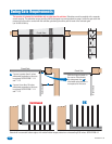
Chassis
Ground
Electrical Box
Knock-outs
Conduit
Neutral
115 VAC
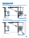
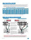
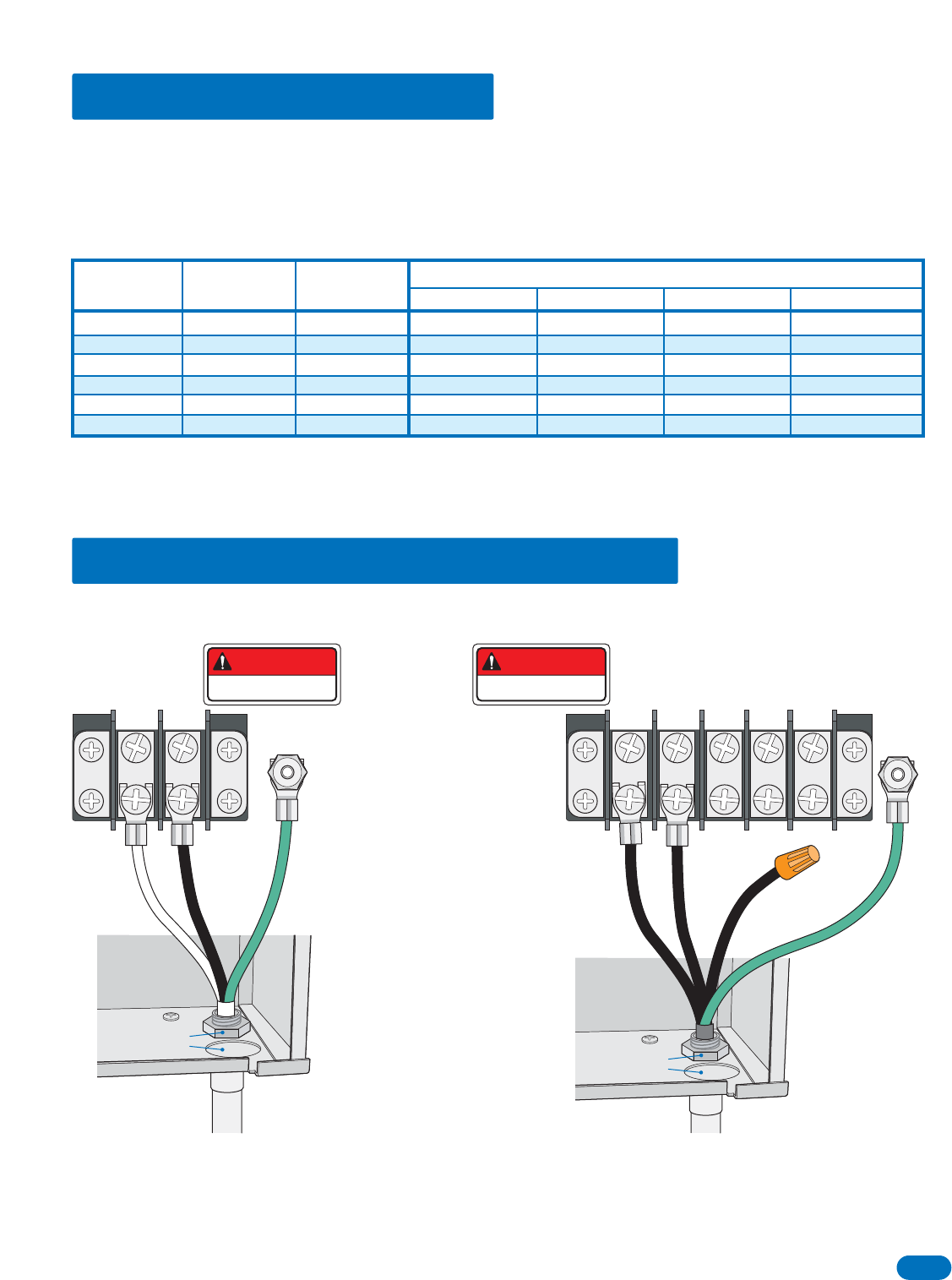
115 VAC Models
Electrical Box
Knock-outs
Conduit
230/460 VAC
230/460 VAC
115 VAC Neu
115 VAC Neu
115 VAC Hot
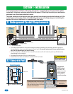
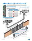
2.1 High Voltage Wire Runs
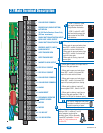
2.2 High Voltage Terminal Connections
The distance shown in the chart is measured in Feet from the operator to the power source. If power wiring is greater than
the maximum distance shown, it is recommended that a service feeder be installed. When large gauge wire is used, a
separate junction box must be installed for the operator connection. The wire table is based on stranded copper wire. Wire
run calculations are based on a 110 VAC power source with a 3% voltage drop on the power line, plus an additional 10%
reduction in distance to allow for other losses in the system.
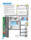
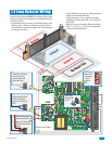
• Route incoming high voltage
power through conduit and into
the operator as shown.
• Be sure wiring is installed in
accordance with local codes. Be
sure to color code all wiring.
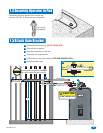
• It is recommended that a surge
suppressor be installed on the
high voltage power lines to help
protect the operator and circuit
board from surges and power
fluctuations.
• Secondary operator in a dual
operator application gets power
through the 8-wire connector that
links the 2 operators together. See
2.7 Primary/Secondary (dual) gate
connection.
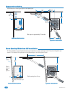
230 VAC/460 VAC Models
Chassis
Ground
DANGER
HIGH VOLTAGE!
DANGER
HIGH VOLTAGE!
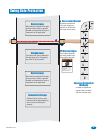
Never run high voltage and low voltage wires in the same conduit. Keep them in separate conduits.
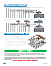
This table illustrates the high voltage wire size and distance requirements.
Reduce the wire distance in half for primary/secondary dual gate applications
Model
Type
Voltage
Required
Amps
Required
Wire Size / Distance in Feet
115 5.4 170 275 460 685
12 AWG 10 AWG 8 AWG 6 AWG
6500 1/2 HP
230 2.7 685 1,100 1,830 2750
6500 1/2 HP
460 1.35 2,875 4,600 7665 11,500
6500 1/2 HP
115 9.7 100 170 280 520
6500 1 HP
230 4.9 380 650 1,100 1,600
6500 1 HP
460 2.5 1,500 2,500 4,000 6,500
6500 1 HP
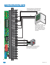
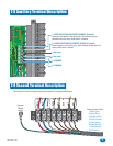
DO NOT cycle the operator without the OPEN and CLOSE limit sensors in their specific open
and close positions.
The limit sensors or the AC power switch are the only ways to stop the operator once
an open cycle has started. This could cause damage to the gate and/or operator if the gate opens too far!
For 230 and 460
Volt 3-phase
input, use only
two legs of the
incoming 3-phase
power.
6500-065-K-7-08