


2
CCH00701:09/00
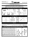
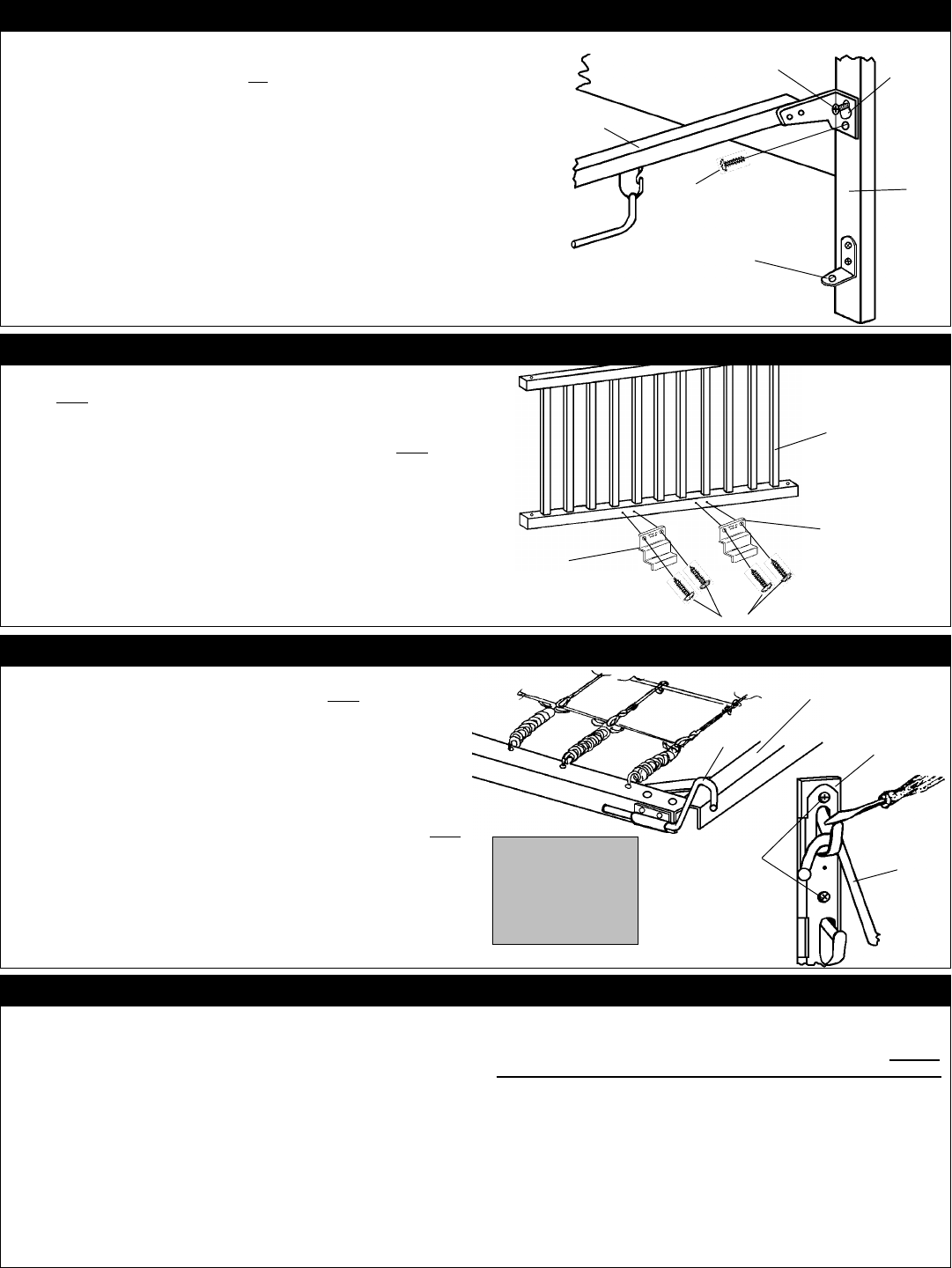
STEP 2 - DIAGRAM 2: INSTALL STABILIZER BARS.
Attach each Stabilizer Bar
JJ
JJ
J to crib ends
NN
NN
N and
OO
OO
O
.
Refer to Diagram 2 and MAIN
DIAGRAM 6. You will use a total of (8) Slotted/Phillips Machine Screws
AA
AA
A. Place a
Slotted/Phillips Machine Screw
AA
AA
A into top receiving bushing, designated for Stabilizer
Bar
JJ
JJ
J placement, located in ends
OO
OO
O &
NN
NN
N as shown, leave each top screw extended
- do not tighten at this time. Place the keyhole
(top hole in each end of Stabilizer Bar
JJ
JJ
J, over top extended Screws
AA
AA
A
(which you have just installed and left extended),
refer
to Diagram.
Ends
NN
NN
N and
OO
OO
O will now be mounted together on one side of crib, repeat
this procedure for mounting the remaining Stabilizer Bar
JJ
JJ
J to the other side of the crib
in the exact same manner. Place four Slotted/Phillips Machine Screws
AA
AA
A into the lower
receiving holes in each end of both Stabilizer Bars
JJ
JJ
J, into receiving bushings located in
ends
NN
NN
N &
OO
OO
O, tighten all eight Slotted/Phillips Machine Screws
AA
AA
A securely at this time.
A
A
Extended
J
I
Factory
installed
Keyhole
O
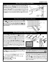
STEP 3 - DIAGRAM 3: ATTACH G ATE S HOES TO D ROPSIDES.
Position two Gate Shoes
CC
CC
C to lower rail
(inside)
of each Crib Side
P/QP/Q
P/QP/Q
P/Q as
shown. Note: Gate Shoe Patent No. will be visible when Gate Shoes
CC
CC
C are
mounted. Align Gate Shoes
CC
CC
C over predrilled lead holes on lower rail
(inside)
of Crib Side
P/QP/Q
P/QP/Q
P/Q
(dropsides)
and affix with (8) Slotted/Phillips Wood Screws
EE
EE
E, two in each Gate Shoe
CC
CC
C
.
Tighten Screws
EE
EE
E securely. Note: When
disassembling crib in the future, DO NOT REMOVE THE GATE SHOES
CC
CC
C OR
ANY OTHER HARDWARE ITEM ATTACHED WITH SLOTTED/PHILLIPS
WOOD SCREWS
EE
EE
E.
E
C
C
P orQ
Locate Crib Spring
RR
RR
R,
(with plastic pouch factory attached)
, and the four
Spring Hangers
BB
BB
B, refer to Main Diagram 6, and 4. Note: Be sure smooth
side of Crib Spring
RR
RR
R wire is placed upward as illustrated in Main Diagram
6. Also the printing on the plastic pouch
(attached to crib spring)
will be
placed upward. Insert Spring Hangers
BB
BB
B into each bracket attached to
frame of Crib Spring
RR
RR
R as shown, (a light blow with a hammer may be
required to fully engage Spring Hangers
BB
BB
B)
.
Carefully install Crib Spring
RR
RR
R by placing each of the 4 Spring Hanger
BB
BB
B into a selected position in each
of the four 4-Position Spring Hanger Brackets
DD
DD
D, (with moulded plastic
backers), mounted on ends
OO
OO
O and
NN
NN
N. See Main Diagram 6, and 4. Note:
The lip of the moulded plastic backer will allow the Spring Hanger to be
placed with no difficulty. However, when you decide on another placement
of Crib Spring
RR
RR
R you will need to place your thumbnail, or a small
screwdriver, on the lip of the moulded plastic backer and hold down in order
to raise Spring Hanger
BB
BB
B from its present position. Follow this same
procedure whenever you opt to change Crib Spring
RR
RR
R to another of the
four positions.
BB
BB
B
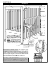
STEP 4 - DIAGRAM 4: INSTALL SPRING H ANGERS & CRIB S PRING
CLOSE UPCLOSE UP
CLOSE UPCLOSE UP
CLOSE UP
VIEW VIEW
VIEW VIEW
VIEW
To remove Spring
Hanger
BB
BB
B press
down on lip with
thumbnail or screw-
driver and pull Spring
Hanger
BB
BB
B upward.
DD
DD
D
EE
EE
E
BB
BB
B
RR
RR
R
Top surface
STEP 5: INSTALL C RIB D ROPSIDES
Locate Crib Rods
KK
KK
K, Crib Sides
P/QP/Q
P/QP/Q
P/Q, Compression Springs
FF
FF
F, Bumper
Springs
GG
GG
G and the four remaining Slotted/Phillips Machine Screws
AA
AA
A. Insert
a Crib Rod
KK
KK
K downward through the holes in the following sequence:
(Refer
to Main Diagram 6 for proper placement.)
Place a Slotted/Phillips Machine Screw
AA
AA
A into hole in top of Crib Rod
KK
KK
K
and into receiving bushing located in top corner post of Footboard
OO
OO
O/
Headboard
NN
NN
N
. Refer
to Main Diagram 6 for proper placement. DO NOT
USE A POWER SCREWDRIVER OF ANY TYPE TO TIGHTEN SCREW
AA
AA
A.
Start Screw A (two or three turns) with your fingers into its threaded
bushing to insure Screw A has a square fit. Once you are sure Screw
A fits squarely into its threaded bushing, tighten securely with a hand
held screwdriver. Attach the other Crib Rod
KK
KK
K to the other end of Crib
Side
PP
PP
P or
QQ
QQ
Q,
,
using the same procedure. Be sure Slotted/Phillips
Machine Screws
AA
AA
A are tightened securely, check periodically and
tighten if needed.
Tip:Tip:
Tip:Tip:
Tip: To help Crib Rods
KK
KK
K function more quietly we
suggest you rub the crib rod with waxed paper or paraffin. You may want
to repeat this procedure periodically. Attach the remaining Crib Side
PP
PP
P
or
QQ
QQ
Q, by repeating Step 5.
1.1.
1.1.
1. The top rail of Crib Side
PP
PP
P or
QQ
QQ
Q,
(with plastic teething rail),
(Note: gate shoes will be placed to inside),
2.2.
2.2.
2. The L- bracket on 4-Position Spring Hanger Bracket
DD
DD
D,
3.3.
3.3.
3. Compression Spring
FF
FF
F,
4.4.
4.4.
4. Bottom Rail of Crib Side
PP
PP
P or
QQ
QQ
Q,
5.5.
5.5.
5. A Bumper Spring
GG
GG
G,
6.6.
6.6.
6. Hole in Angle Bracket
II
II
I.