


Setup
ST-800X User Manual 9 2007-03-07/10:58
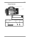
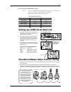
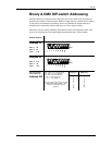
This drawing provides a
general illustration of
the DMX Input/Output
panel of a lighting
Universal DMX Controller
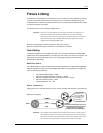
Continue the link
Often, the setup for Master-Slave
and Standalone operation
requires that the first fixture in the
chain be initialized for this
purpose via either settings in the
control panel or DIP-switches.
Secondarily the fixtures that
follow may also require a slave
setting. Please consult the
“Operating Instructions” section
in this manual for complete
instructions for this type of setup
and configuration.
Fixtures displayed are for illustration purpose only!
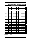
3-Pin to 5-Pin Conversion Chart
Note! If you use a controller with a 5 pin DMX output connector, you will need to use
a 5 pin to 3 pin adapter. CHAUVET Model No: DMX5M.
The chart below details a proper cable conversion:
3 PIN TO 5 PIN CONVERSION CHART
Conductor 3 Pin Female (output) 5 Pin Male (Input)
Ground/Shield Pin 1 Pin 1
Data ( - )signal Pin 2 Pin 2
Data ( + ) signal Pin 3 Pin 3
Do not use Do not use
Do not use Do not use
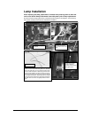
Setting up a DMX Serial Data Link
1. Connect the (male) 3 pin connector side of
the DMX cable to the output (female) 3 pin
connector of the controller.
2. Connect the end of the cable coming from
the controller which will have a (female) 3
pin connector to the input connector of the
next fixture consisting of a (male) 3 pin
connector.
3. Then, proceed to connect from the output
as stated above to the input of the following
fixture and so on.
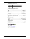
CHAUVET Certified DMX Data Cables
Order Code Description
DMX1.5 DMX Cable 1.5m/4.9ft
DMX4.5 DMX Cable 4.5m/14.8ft
DMX10 DMX Cable 10m/32.8ft
Standalone/Master-Slave Fixture Linking
4. Connect the (male) 3 pin connector side of the DMX cable to the output (female) 3 pin connector
of the first fixture.
5. Connect the end of the cable coming from the first fixture which will have a (female) 3 pin
connector to the input connector of the next fixture consisting of a (male) 3 pin connector. Then,
proceed to connect from the output as stated above to the input of the following fixture and so on.