


AGE RECOMMENDATIONS:
We do not recommend that children under 8 weeks old be placed in the stroller seat.
For jogging and off road use, we recommend that children not be younger than 8 months
old. Young babies incapable of holding their head up must be provided additional head
and neck support to ride safely.
Children develop at different rates. Consult with your pediatrician regarding the suitability
of stroller use with your child.
ASSEMBLY INSTRUCTIONS:
Reference Fig. 1 as it describes various parts of the stroller.
WHAT YOUR STROLLER BOX SHOULD CONTAIN:
.
Stroller
.
Wheels (2 rear, 1 front)
.
Fender (inside poly bag)
.
Front Wheel Quick Release (inside poly bag)
.
This Owners Manual
1. UNPACK:
Remove stroller, stroller wheels, front fender and front quick release from packaging.
Plastic packaging material was used to protect the front fork dropouts, the front wheel
axles, handlebar release levers and the metal shock brackets. Remove and discard
packaging material to avoid choking and suffocation hazards.
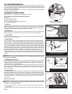
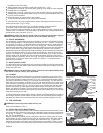
2. SWING ARM:
Rotate the swing arm away from the front of the stroller until the shocks engage in the
first position (Fig. 2). Each shock locking pin will snap and lock into position 1.
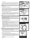
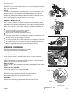
3. HANDLEBAR:
Rotate the stroller handlebar up to the fully open position. Make sure Slider Latches
lock into place as shown in Fig 3.
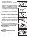
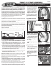
4. REAR WHEEL:
Prior to installing the rear wheels, position the brake bar in the Unlocked position as
shown in Fig. 17. Place the rear wheel quick release cam lever in the open position,
as shown in Fig. 4. Insert the rear wheels stub axle into the hole in the rear dropout.
If the axle does not slide in easily, loosen the quick release tension adjusting nut (Fig.
4) by hand. Re-insert the axle fully into the rear dropout until the axle shoulder or snap
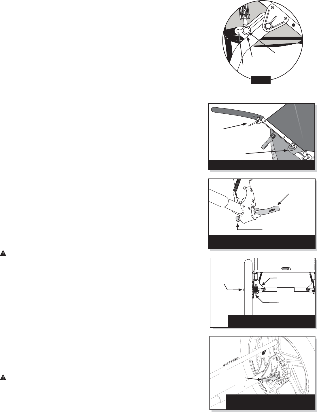
ring on the axle comes in contact with the dropout (Fig. 5). Move the quick release cam
lever to the closed position (Fig. 6). The word CLOSE should be clearly visible and the
quick release cam lever should almost touch the dropout. When properly adjusted, it
will require considerable force (37-50lbs or 165-222N) to close the lever. If you do not
feel this resistance (too loose or too tight), return the quick release cam lever back to
the open position (Fig. 4), and adjust the tension adjusting nut (clockwise to tighten,
counterclockwise to loosen). Move the quick release cam lever to the closed position
(Fig. 6).
WARNING: Failure to properly adjust quick release may result in wheel loss and
serious personal injury. If you are unsure how to operate the quick release, consult
your dealer or call BOB.
5. FENDER INSTALLATION:
Before installing the front wheel, you will need to attach the fender. The two attachment
screws can be found already installed on the frame (Fig. 7). Remove the two fender
mounting screws. You may wish to remove a fabric screw (right or left) to give better
access to the cross tube fender screw.
Align the hole in the metal tab of the fender with the threaded hole in the center of the
front cross tube and install screw (Fig. 8). Align the hole in the plastic fender with the
hole in the brake mounting plate and install screw (Fig. 8). Center fender on stroller and
tighten both screws.
6. FRONT WHEEL:
Its important to your safety, performance and enjoyment to understand how the front
wheel quick release works on your stroller. We urge you to ask your dealer how to do
the things described in this section before you attempt them yourself, and that you have
your dealer check your work before you use the stroller. If you have even the slightest
doubt as to whether you understand something in this section of the Manual, talk to
your dealer.
Wheel Quick Release
WARNING: Strolling with an improperly adjusted wheel quick release can allow
the wheel to wobble or fall off the stroller, which can cause serious injury or death.
Therefore, it is essential that you:
.
Ask your dealer to help you make sure you know how to install and remove your
wheels safely.
.
Understand and apply the correct technique for clamping your wheel in place with
Fig. 3 Handlebar in the fully open position
Handlebar Release
Lever
Slider Latch
Quick Release
Cam Lever Open
Tension Adjusting Nut
Fig. 4 Rear wheel Quick Release with
Cam Lever in open position
Fig. 5 Rear wheel properly installed
Snap Ring or
Axle Shoulder
Dropout
Insert
Wheel
Fully
Quick
Release
Closed
Fig. 6 Quick Release Cam Lever in the
closed position (right side shown)
Position 1
Shock
Release
Button
Position 2
Swingarm in unfolded position
with shock in position 1
Fig. 2
P2OMS01A