


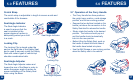
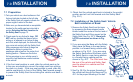
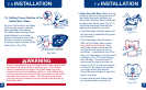
7.4 Setting Proper Recline of the
Safety Seat / Base
For your child’s safety, the Safety
Seat must be properly reclined
when installed in the vehicle.
The Safety Seat includes a Seat
Angle Indicator on the lower
portion of the shell on the child’s
left side, to assist in achieving
the proper angle of recline for the
Safety Seat. (Fig. 46-2)
7.0 INSTALLATION
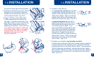
4746
Press to release
Use weight range as appropriate
See warning label on safety seat
Fig. 46-1b
Fig. 46-2
Fig. 46-1a
C
O
R
R
E
C
T
W
R
O
N
G
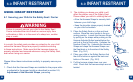
20 pounds
(9 kg) and
under
2
0
t
o
3
0
p
o
u
n
d
s
(
9
t
o
1
3
.6
k
g
)
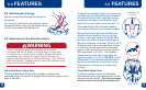
Failure to properly recline the Safety Seat on the vehicle seat
increases the risk of death or serious injury. If the Safety
Seat is positioned too upright, the child’s head may drop
forward and result in breathing problems. If the Safety Seat
is too reclined, excessive force may be exerted on the child’s
shoulders and neck in a crash. The following instructions
must be carefully followed to ensure proper recline angle for
the Safety Seat.
WARNING
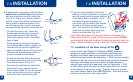
7.0 INSTALLATION
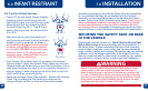
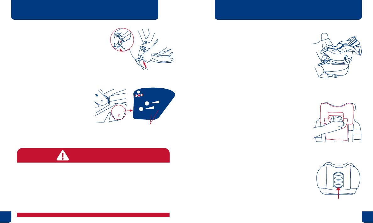
1. Safety Seat with Base: Make sure the
vehicle is parked on level ground. Lock
the Safety Seat onto the Base and
check that the Safety Seat is level side
to side on the vehicle seat. (Fig. 47-1)
Check the Seat Angle Indicator that
matches the weight of your child.
• If the Seat Angle Indicator shows NO
red, the seat is installed at the proper
level of recline.
• If the Seat Angle Indicator shows
ANY red, the Safety Seat is either
too upright or too reclined. If the
seat is too upright, extend the foot
one position at a time just until no
red shows. To extend the foot of the
base, pull downward on the hand hold
as shown in Fig. 47-2 while holding
onto the base. To retract the foot,
press inward on the lock button as
shown in Fig. 47-3 and push upward
on the foot. Be careful not to pinch
your nger as the foot retracts.
Check the level indicator to see if the
seat is now level.
• If seat angle adjuster feature does
not adjust enough to provide the
Fig. 47-1
Fig. 47-2
Fig. 47-3
Foot Adjustment
Lock Button