


Decoder for Atlas N Scale H15/16-44 Locomotives
5
Atlas Model Railroad Co., Inc.
Step by Step Installation
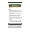
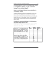
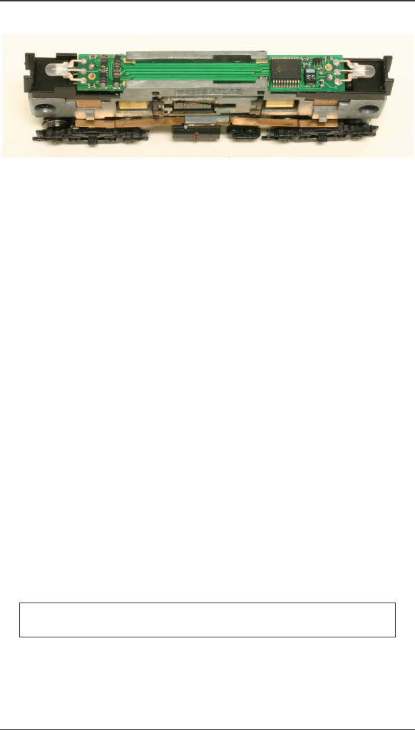
Figure 1: Installing the H15/16-44 decoder
In the following steps, please refer to the instructions provided with your
Atlas locomotive.
1) Remove the locomotive's body shell and fuel tank. Use care so as
not to damage any of the fragile parts.
2) Loosen the two screws that hold the frame together; these screws
are located at the front and rear of the frame.
3) Carefully remove the lighting control circuit board, which is located
at the top of the frame.
4) Place the decoder between the two halves of the frame so that the
two motor contact pads are at the bottom of the decoder and will
press firmly against the two copper contact strips from the motor
when the decoder installation has been completed. In the
photograph of the bottom of the H15/16-44 decoder on the first
page, these motor contact pads are the two rectangles in the
narrow center portion of the circuit board.
5) Carefully press the two frame halves together, with the sides of the
decoder inserted into the notches in the two halves of the frame.
Some pressure is needed to press the two frame halves together.
This pressure fit insures good electrical contact between the frame
and the decoder.
6) Tighten the two screws that hold the locomotive frame together.
7) Carefully check to make sure that the motor contact strips are not
touching either half of the frame. It is necessary to look down from
the top through the frame cutouts to check for such unwanted
shorts.
There must be NO electrical contact between the motor
contacts and any part of the frame
Place the locomotive (without its body shell) on your DCC programming
track and read back the locomotive's address from the decoder. If the
decoder is properly installed, you will be able to read back the factory
pre-set address 03. If your DCC system does not support reading