1
5
9
3
7
11
2
6
10
4
8
12
13
14
2
2
1
1
B
B
A
B
B
A
21
7 – Wiring (continued)
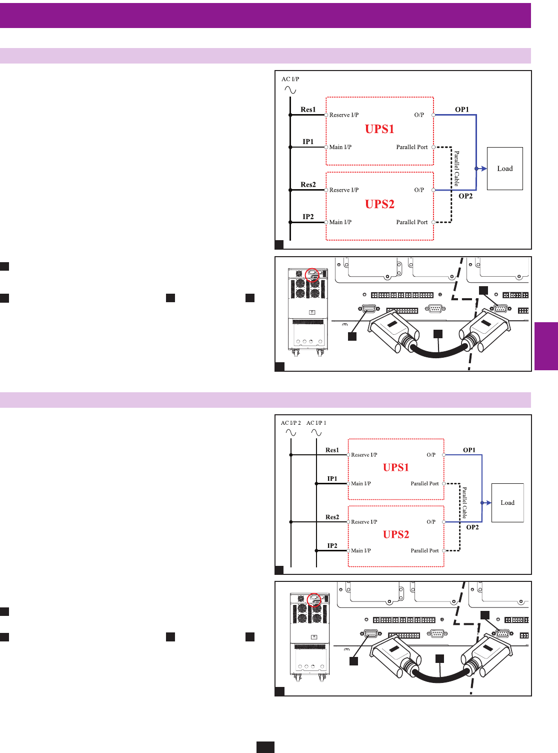
7-8 AC Input/Output Wiring (Parallel UPS – Single Input Source)
Parallel UPS Warnings:
The total input cable length must be equal to the total •
output cable length in order to prevent unbalanced load
sharing between two UPS systems under reserve mode
(i.e. Res1 + OP1 = Res2 + OP2; deviation must be <10%).
Parallel configuration only supports 2 UPS systems (1+1 •
redundancy or capacity). Do not attempt to link more than
two UPS systems via parallel configuration.
The UPS systems must have the same rating and capacity •
for parallel UPS installation. Attempting to link
dissimilar UPS systems will damage the UPS systems
and create a serious risk of personal injury and property
damage.
Each UPS must have its Parallel group set to 2 and a •
different “Parallel ID” that indicates the UPS systems are
being run in parallel. (See Section 10-5-5 for more details.)
Follow the steps in • Section 7-7, wiring the UPS systems as shown
in the diagram.
Connect the included parallel UPS cable•
A
to the parallel port
B
of each UPS system.
7-9 AC Input/Output Wiring (Parallel UPS – Dual Input Sources)
Parallel UPS Warnings:
The total input cable length must be equal to the total •
output cable length in order to prevent unbalanced load
sharing between two UPS systems under reserve mode
(i.e. Res1 + OP1 = Res2 + OP2; deviation must be <10%).
Parallel configuration only supports 2 UPS systems (1+1 •
redundancy or capacity). Do not attempt to link more than
two UPS systems via parallel configuration.
The UPS systems must have the same rating and capacity •
for parallel UPS installation. Attempting to
link dissimilar UPS systems will damage the UPS systems
and create a serious risk of personal injury and property
damage.
Each UPS must have its Parallel group set to 2 and a •
different “Parallel ID” that indicates the UPS systems are
being run in parallel. (See Section 10-5-5 for more details.)
Follow the steps in • Section 7-7, wiring the UPS systems as shown
in the diagram.
Connect the included parallel UPS cable •
A
to the parallel port
B
of each UPS system.
1
1
2
2


