16
T1
C1
C2
B1
7 – Parallel Redundancy Operation (Optional)
DANGER! LETHAL HIGH VOLTAGE HAZARD!
All wiring should be performed by a qualified electrician, in accordance with the warnings in this manual and all applicable
electricalandsafetycodes.Incorrectwiringmaycauseseriouspersonalinjuryandpropertydamage.Read,studyand
understand the warnings listed in Section 2 – Important Safety Instructions before proceeding.
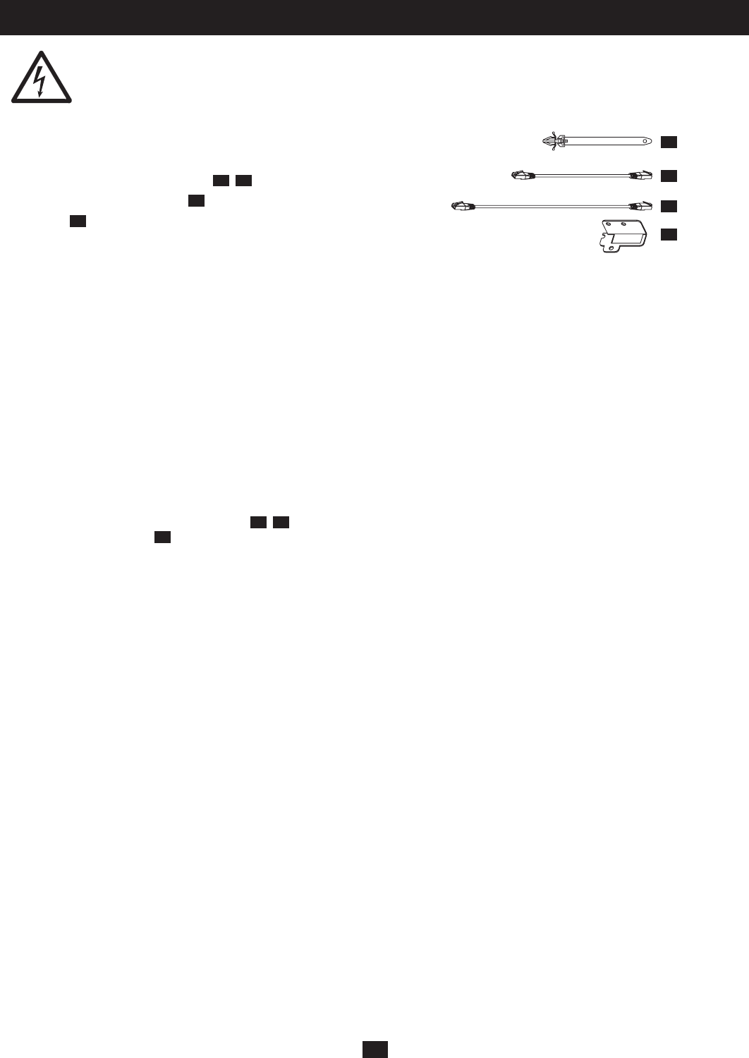
Unpacking the Parallel Kit
Theparallelkitshouldincludetheseparts:
•2RJ45ParallelCommunicationCables
C1
,
C2
•1ParallelCommunicationBracket
B1
•1CableTie
T1
UPS System Placement
InordertominimizethepossibilityofdamagetotheUPSsystemandmaximizeitsoperationallifespan,followthelocationwarningslistedin
Section 2 – Important Safety Instructions. Remember to keep at least 30 cm clearance from the rear panel of the UPS system to the wall and
do not block any of the UPS system’s front or rear ventilation openings.
Warning: The UPS system is very heavy—be careful when moving or lifting it.
Installation
1. To avoid noise interference, install each wire and cable separately to the input, output and battery.
2. Keepallinput,outputandbatterywiresandcablesawayfromallconnectingwiresforparallelfunctionsandcontrolsignals,includingRJ45,
RS-232,RS-485,USBandEPO.Ifthisisnotpossible,setthemat90°anglesoratleast20cmapart.
3. Warning:TheUPSsystemincludesanEMIfilter.Topreventpotentialleakageofhazardouscurrent,confirmthattheACsupply
circuit is securely grounded.
Start-up Procedure
1. Position the UPS systems as specified above.
2. Connect the parallel communication cables
C1
,
C2
tothe“Ring”loopatamaximumlengthof7m.Securethecableswiththeparallel
communication brackets
B1
.
3. ArrangethepowercablesandthecontrolsignalcablesaccordingtoUPStype.Makesurethatallcircuitbreakersattheinputandoutput
ends are set to OFF.
4. For maintenance purposes, you may wish to purchase a manual bypass master panel (optional).
5. SettheterminalresistorsofonlytwoparallelUPSsystemstotheONposition.(Forthreeunitsinparallel,switchontheterminalresistorsof
UPS#1and#3only.Forfourunitsinparallel,switchontheterminalresistorsofUPS#1and#4only.)
6. Turnontheutilityinputbreaker.ConfigureeachUPSsystem’soperatingmodetoparallelmode(P02)andsettheIDs(e.g.UPS1,ID=1)of
the respective UPS systems. (See Section 6-6 – UPS System Settings and Measurements.)AllparallelUPSsystemparametersexceptID
number must be same, including the number and type of connected battery packs.
7. Ifanexternalmanualbypassmasterpanel(optional)isinstalled,makesuretheswitchisinthe“Bypass”position.ChecktoseeiftheUPS
system is in bypass mode with output voltage available.
8. Turn on the output breaker and ensure that the connected loads are supplied with power via the manual bypass master panel.
9. TurnontheoutputbreakeroftheUPSandturntheswitchofthemanualbypassmasterpanelto“UPS”position.Theconnectedloadswill
be supplied with power via the UPS bypass loop.
10. TurnoneachUPSsystemindividuallyandmakesureitisininvertersupply(normal)mode.Installationisnowcomplete.


