2
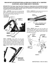
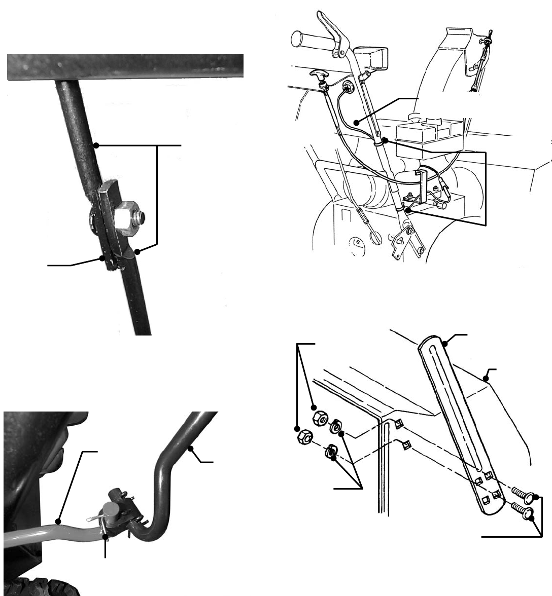
STEP 5: CONTROL ROD: : Cut wire ties that secure the
ground speed control handle and control rods. Secure both
halves of the ground speed control rod together.
IMPORTANT: Make sure alignment tab and slot on the
two rod halves are engaged together. Tighten nut securely.
See Figure 5.
FIGURE 5
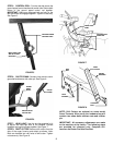
STEP 6: CHUTE CRANK: Connect chute crank to worm
gear shaft and secure with cotter pin. See Figure 6.
FIGURE 6
STEP 7: HEAD LIGHT: Use the wire ties supplied in kit
to secure the head light wire to the handles. Connect
headlight and engine harness together. See Figure 7.
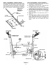
STEP 8: DRIFT CUTTER Remove drift cutters from the
side of the auger housing and attach as shown. Note:
Bolts are inserted into rear holes of drift cutter. Tighten
nuts securely. See Figure 8.
FIGURE 7
FIGURE 8
NOTE: Drift Cutters are optional on some model
Snow Throwers. After set-up the hardware bag will
contain: two shear bolts and two nuts and a cotter
pin.
IMPORTANT: All necessary adjustments are made
to the machine at the factory. The following steps
are provided for reference only. Complete ALL
items on the Dealer Pre-Sale Checklist.
CARRIAGE
GROUND SPEED
CONTROL ROD
MAKE SURE TAB
AND SLOT ARE
ENGAGED
CHUTE
CRANK
SECURE WITH
COTTER PIN
WORM
GEAR
SHAFT
HEAD LIGHT
WIRE
SECURE WITH
WIRE TIES
DRIFT
CUTTER
HEX
NUT
LOCK
WASHER
AUGER
HOUSING