9
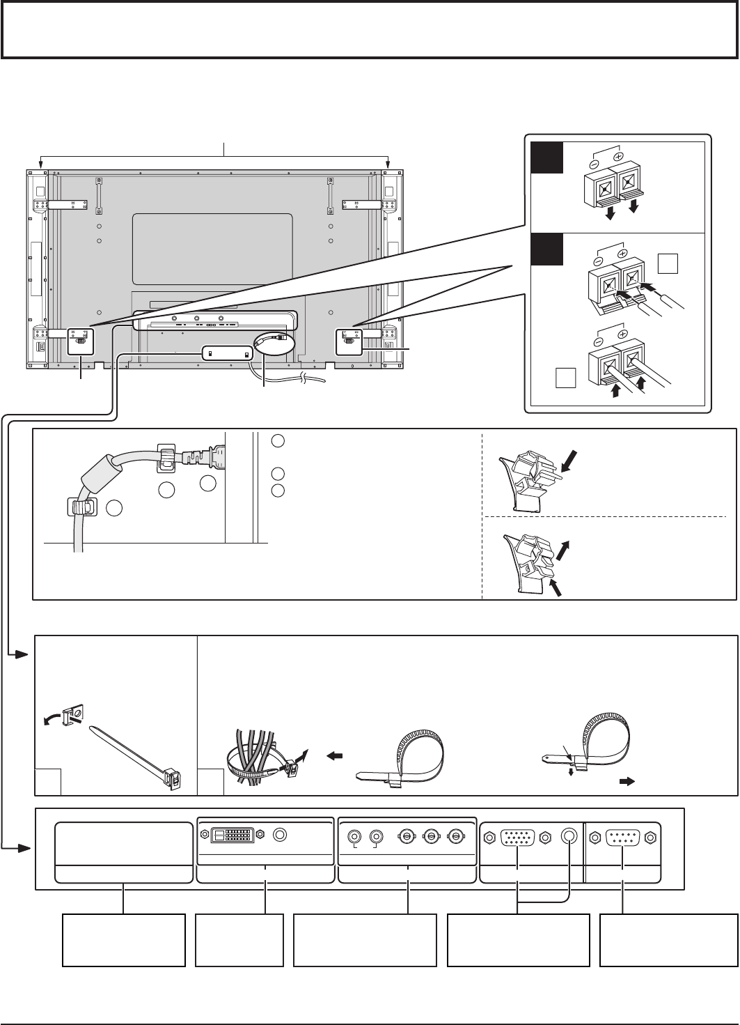
Connections
1
3
2
1
2
1
2
1
2
SERIALPC IN
AUDIO
SLOT1 SLOT3
P
R
/C
R
/R P
B
/C
B
/B
Y/G
AUDIO
RL
COMPONENT/RGB IN
SLOT2
AUDIO
DVI-D IN
SPEAKERS
Terminals (R)
SPEAKERS
Terminals (L)
– Cable fi xing bands
Secure any excess cables with bands as required.
When connecting the speakers, be sure to use only the optional accessory speakers.
Refer to the speaker’s Installation Manual for details on speaker installation.
Speakers (Optional accessories)
Pass the attached cable
fi xing band through the
clip as shown in the
fi gure.
To secure cables connected to Terminals, wrap the cable fi xing band around them then
pass the pointed end through the locking block, as shown in the fi gure.
While ensuring there is suffi cient slack in cables to minimize stress (especially
in the power cord), fi rmly bind all cables with the supplied fi xing band.
From SERIAL
Terminal on Computer
(see page 11)
From EXTERNAL
monitor terminal on
Computer (see page 10)
AC cord connection (see page 13)
DVI-D IN
Terminals
(see page 12)
To tighten:
To loosen:
Pull
Pull
Push the catch
Note:
At factory shipment, Terminal boards are installed in SLOT 2 and SLOT 3.
– AC cord fi xing
Optional Terminal
Board Insert Slot
(covered)
COMPONENT/RGB IN
and Audio IN Terminals
(see page 12)
Note: The power plug in the illustration may not be the type fi tted to
your set.
1
Connect the AC cord plug to
the Plasma Display.
2
Fix the left side clamper.
3
Fix the right side clamper.
Close
Open
Push until the hook clicks.
2. Pull off.
1. Keep the knob pressed.


