21
W415-0533 / E / 02.09.06
INSTALLATION TO
BE DONE BY A
QUALIFIED IN-
STALLER and must
be electrically con-
nected and
grounded in accord-
ance with local
codes. In the
absense of local
codes, use the cur-
rent CSA C22.1 CA-
NADIAN ELECTRICAL CODE
in Canada or the
ANSI/NFPA 70 NA-
TIONAL ELECTRICAL CODE in the United States
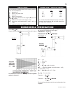
If the fireplace was not
previously equipped
with a blower: route a
grounded 2-wire, 60hz
power cable to the recep-
tacle / junction box. At this
point, it must be strain re-
lieved and insulated.
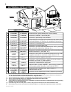
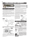
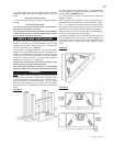
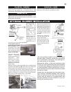
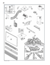
The three slots on the
blower mounting
bracket allow ease of
adjustment when
attaching the blower.
For a quiet running
blower, do not allow the
assembly to sit on the
firebox base.
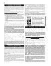
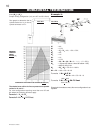
Slide the vibration reducing pad (A) into the clip (C) and up
against the threaded stud (B) at the other end. The blower
must be able to be positioned entirely onto the pad.
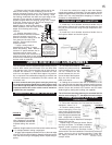
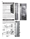
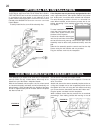
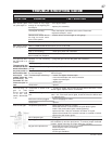
Tilt the blower onto its side. Slide it past the controls and
into the clip (C). Secure to the threaded stud using the lock
washer and wing nut provided. Ensure that the blower
does not touch the fireplace base or the firebox.
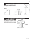
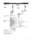
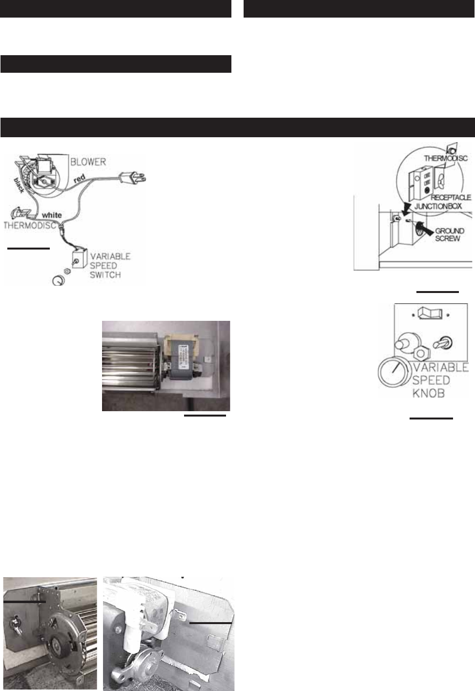
Attach the connectors from the
black and white wires to the
thermodisc and secure the
thermodisc bracket to the se-
curing stud at the bottom left
of the unit using a lock washer
and wing nut. Ensure that the
thermodisc touches the fire-
box wall.
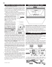
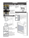
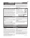
Attach the connectors
from the black and red
wires to the blower.
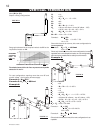
Attach and secure the vari-
able speed switch using
the nut provided. Plug the
harness cord into the re-
ceptacle.
The wire harness provided in this kit is a universal
harness. When installed, ensure that any excess
wire is contained, preventing it from making con-
tact with moving or hot objects.
Because the blower is thermally activated, when
turned on, it will automatically start approximately
10 minutes after lighting the fireplace and will run
for approximately 30-45 minutes after the fire-
place has been turned off. Use of the fan increases
the output of heat.
Drywall dust will penetrate into the blower bear-
ings, causing irreparable damage. Care must be
taken to prevent drywall dust from coming into
contact with the blower or its compartment. Any
damage resulting from this condition is not cov-
ered by the warranty policy.
FIGURE 41
FIGURE 45
FIGURE 46
FIGURE 42
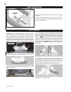
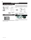
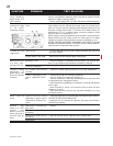
CHARCOAL EMBERS
VERMICULITE
CHARCOAL LUMPS
OPTIONAL BLOWER INSTALLATION
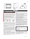
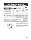
Randomly place the charcoal embers along the front and
sides of the log support tray in a realistic manner. Fine
dust found in the bottom of the bag should not be used.
Sprinkle vermiculite around the charcoal embers.
Note: Both charcoal embers and vermiculite are not to
be placed on the burner.
Place the lumps between the logs in a realistic manner
taking care not to block any of the burner ports.
C
A
B
FIGURE 43
FIGURE 44