25
6. SETTING ON THE MENU SCREEN (Cont’d)
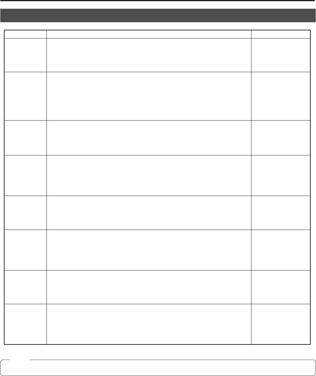
TOTAL SETTING SCREEN
Note:
The data set at the TOTAL SETTING is common to all files.
Item
D-SUB OUT RGB
COMPONENT
ON SYNC OFF
G
RGB
INDICATOR OFF
ON
H PHASE
SC COARSE 0
90
180
270
SC FINE
Functions and operation Variable values
+127
to
0
to
–128
+127
to
0
to
–128
This carries the SC COARSE adjustment when the phase for the VBS signal input
from the HD.VBS connector on the rear panel of the KY-F58 is synchronized.
Carry it out together with the SC FINE adjustment.
By carrying out together with the SC COARSE adjustment, it finely adjusts the sub
carrier.
It adjusts the horizontal phase when synchronization is carried out at EXT REF
connectors (HD/VBS and VD) on the rear panel of the KY-F58.
It sets whether to display the values of GAIN, SHUTTER and IRIS on each output
connector.
OFF : No display
ON : Display
This selects the signals output from the RGB/COMPONENT output connector on
the rear panel of the KY-F58.
RGB : RGB signal is output.
COMPONENT : Y/R-Y/B-Y signals are output.
It sets the SYNC signal to add to the RGB signals output from the RGB/COMPONENT
output connector on the rear panel of the KY-F58. (Only available when the D-SUB
OUT is set to RGB.)
OFF : SYNC signal is not added.
G : SYNC signal is added only at G singnal.
RGB : SYNC signal is added to all R, G, B signals.
LENS
CONTROL
CONTROLLER
RS-S3SC
This sets whether to control a connecting lens; from the LENS REMOTE connector
on the rear panel of KY-F58 or from RS-232C connector.
The CONTROLLER: LENS is controlled from the LENS REMOTE connector.
The RS-232C: LENS is controlled from the RS-232C connector.
CABLE
LENGTH
5M
10M
15M
20M
25M
Set this according to the cable length between camera head and camera control
unit (CCU).
If the setting is wrong, normal video output may not be obtained.


