Maintenance and Troubleshooting
89ESL E-Series Tape Library User’s Guide
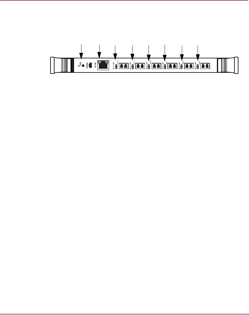
See Figure 34 for LED locations and functions on the e2400-FC 2G interface
controller.
Figure 34: e2400-FC 2G interface controller illustration
Basic troubleshooting
Simplify the installation by reducing it to the most basic configuration. Then, add
elements one at a time, verifying the operation after each step.
Basic troubleshooting includes verifying the setup and the connections, including:
■ Verifying SCSI bus configuration
■ Verifying FC port connection
■ Verifying FC and SCSI devices in Windows NT
■ Verifying the interface controller configuration
■ Verifying devices
■ Verifying host configuration
■ Verifying HBA device driver information
■ Verifying serial port configuration
Each of these topics is discussed in the following sections.
1 FC drive port TD3 LED
2 FC drive port TD2 LED
3 FC drive port TD1 LED
4 FC drive port TD0 LED
5 External port FC1 LED
6 External port FC0 LED
7 Ethernet port LED
8 Interface controller LED
125
67834


