E-12
0 Component video input terminal (COMPONENT VIDEO INPUT)
Connect this terminal to the component video output (color difference output) terminal of your HDTV unit or DVD player.
A S-video input terminal (S-VIDEO INPUT)
Connect this terminal to the S-video output terminal of your VCR or video disk player.
B Video input terminal (VIDEO INPUT)
Connect this terminal to the video output terminal of your VCR or video disk player.
C Power input terminal
Connect this terminal to the power cable supplied with the display.
D Built-in speaker
Produces sound received through the sound input terminal.
Description of Input Terminals
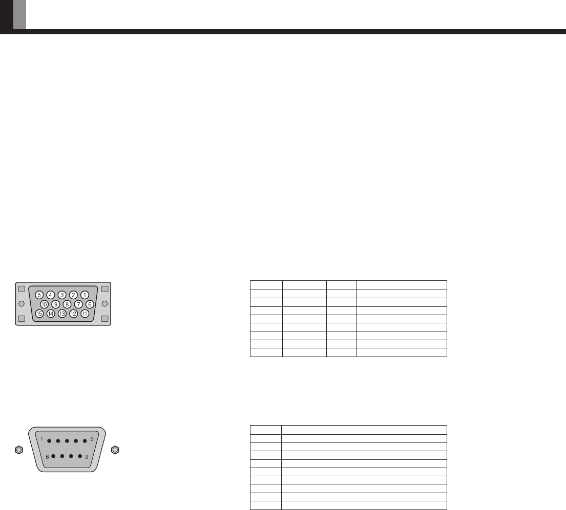
RGB1 input terminal (RGB1 INPUT/mD-sub)
Pin No. Input signal Pin No. Input signal
1 Red 9 —
2 Green 10 Ground
3 Blue 11 —
4 — 12 —
5 Ground 13 Horizontal (H) synchronization
6 Ground 14 Vertical (V) synchronization
7 Ground 15 —
8 Ground Frame Ground
* Use the RGB1 synchronization switch to switch between TTL and ANALOG
depending on the types of horizontal (H) and vertical (V) synchronization signals
received through pins 13 and 14, respectively.
Pin No. Signal
1 DCD (Data Carrier Detect)
2 RD (Received Data)
3 TD (Transmit Data)
4 DTR (Data Terminal ready)
5 GND (Ground)
6 DSR (Data Set Ready)
7 RTS (Request To send)
8 CTS (Clear To Send)
9 RI (Ring Indication)
RS-232C terminal (RS-232C)
PART NAMES AND FUNCTIONS (Continued)


