220
CHAPTER 9 12-BIT PPG TIMER
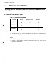
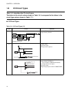
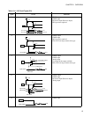
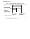
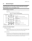
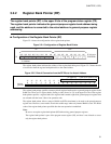
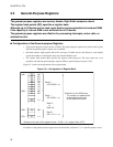
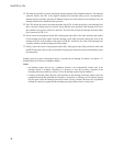
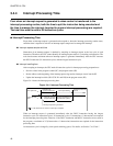
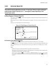
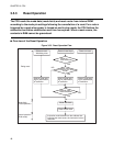
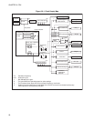
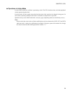
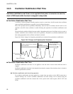
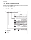
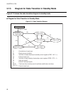
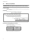
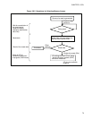
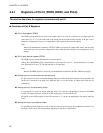
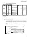
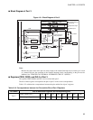
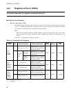
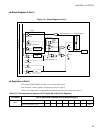
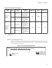
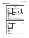
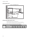
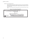
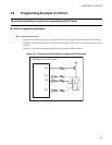
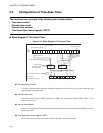
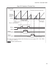
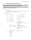
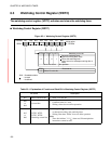
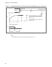
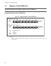
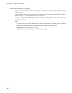
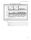
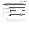
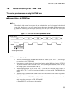
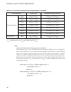
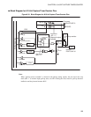
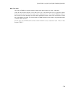
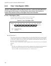
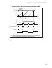
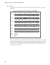
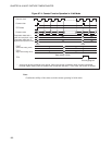
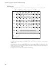
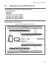
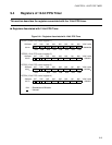
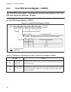
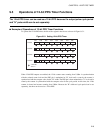
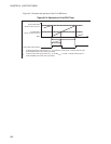
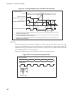
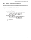
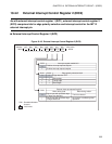
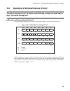
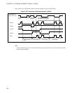
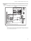
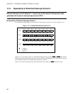
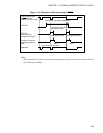
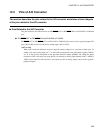
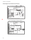
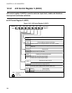
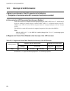
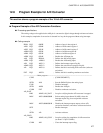
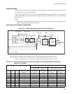
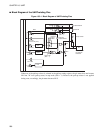
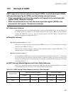
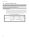
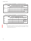
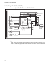
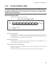
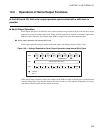
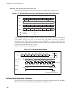
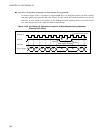
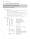
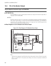
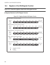
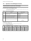
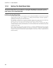
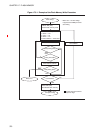
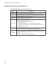
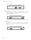
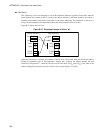
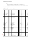
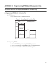
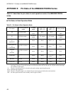
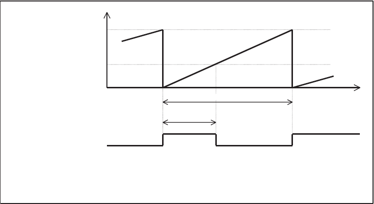
Figure 9.5-2 illustrates the operation of the 12-bit PPG timer.
Figure 9.5-2 Operation of 12-bit PPG Timer
(RCR23, 24:SCL0 to SCL11)
(RCR21, 22:HSC0 to HSC11)
"000
H
"
Count by counter
Cycle period setting
"H" width setting
Cycle period
(*1)
"H" width
(*2)
PPG output pulse waveform
*1:
If internal count clock cycle period is 2, 4, 16, or 256 t
INST
, cycle period = compare value for cycle
period multiplied by the count clock cycle period.
*2:
If internal count clock cycle period is 2, 4, 16, or 256 t
INST
, "H" width = compare value for the "H"
width multiplied by the count clock cycle period.