User’s Manual
26
32.3. Cash Drawer Interface
Make sure the printer is switched off.
Disconnect the printer from the PC and from the power supply
Unscrew the cartridge from the rest of the printer.
Hold the printer and move the cartridge towards the screw hole; at the same time, hold down
the clips that are holding the cartridge in its working position.
When the cartridge reaches its final position you can pull it away from the printer.
Now detach the interface card as described in the Dip Switch item.
Open the cartridge by holding the cover and move the other part (with the ON/OFF switch)
towards the connectors and to the final position, as shown by the pictures below. Now you can
remove the cover.
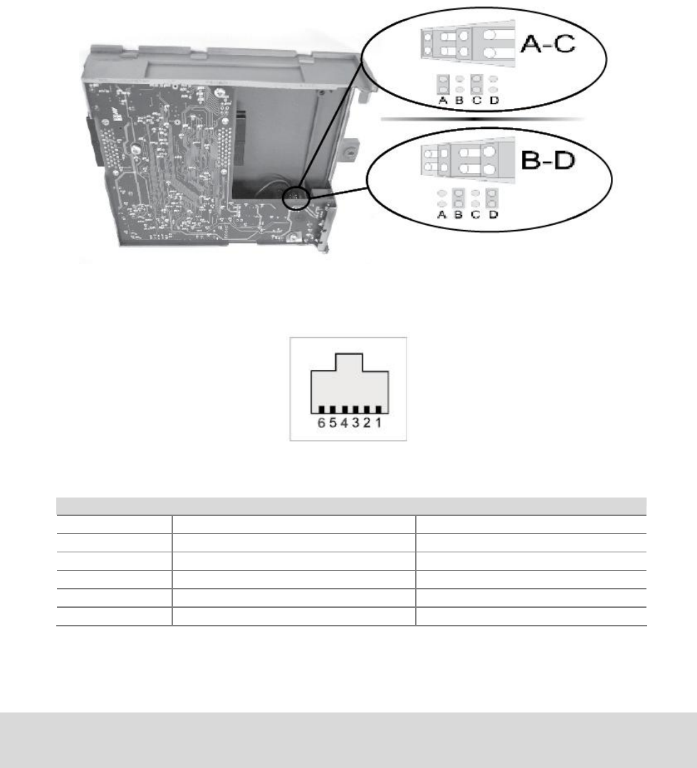
You will find the jumpers in the area shown by the picture below.
The drawer connector pin layout is described below:
Drawer configuration
Drawer type Others (A-C) Bematech/Epson (B-D) **
1 GND Drawer open/close signal
2 Drawer kick out signal Drawer kick out signal
3 Drawer open/close signal 24V
4 24V 24V
5 NC NC
6 GND GND
** Factory Default
Make sure your drawer’s pin layout corresponds exactly to the above before making any
connection. Incorrect drawer pin layouts may damage the printer.
ATTENTION!
This printer controls only one cash drawer.


