22
■
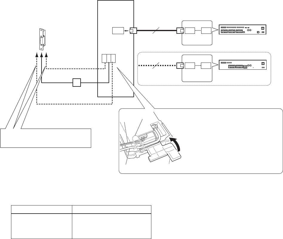
Connections (IS-DV and IS-DVF)
D
NO
COM
NC
PT
300m (980')
D1
D4
CAT5e/6
300m (980')
D1
D8
CAT5e/6
φ0.65-1.2mm
(22-16 AWG)
10m (33')
φ0.65-1.2mm
(22-16 AWG)
10m (33')
φ0.65-1.2mm
(22-16 AWG)
10m (33')
*1: Output specifi cations
Output method N/O or N/C dry closure contact
Voltage between
terminals
24V AC, 0.5A (resistive load)
24V DC, 0.5A (resistive load)
Minimum overload (AC/DC):
100mV, 0.1mA
NOTES:
Do not use the unoccupied terminals and ports for other purposes.
•
In order to prevent miswiring, label both ends of each cable with the unit and terminal names to which they are to be connected.
•
For connecting other manufacture’s products, refer to the instruction manuals for those products.
•
The illustration of the unit’s rear panel differs from the actual one. This is for simplifying the connection diagram.
•
Central control unit
(IS-CCU)
Add-on control unit
(IS-SCU)
AC transformer
or
The terminals are inside the terminal
*
cover. After connecting, route the
wires through the wiring paths, then
close the cover.
Be sure to route the CAT5e/6 cable
*
and option wires through inlet.
When closing the terminal cover,
*
close it until it clicks.
Electric door strike
*1
(non-shielded)
(non-shielded)
(Select one port.)
(Select one port.)
Terminal cover
Inlet
CAT5e/6 cable
Option
wires
Connect to the electric door strike
*
according to its specifi cations.


