


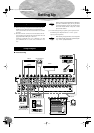
Front & Rear Panels
MG16/4, MG12/4
20
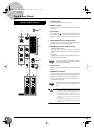
1
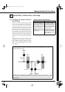
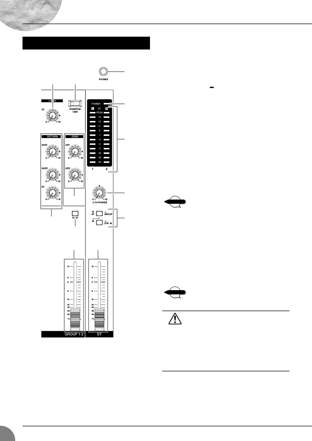
ST Master Fader
Adjusts the signal level to the ST OUT jacks.
2
GROUP 1-2 Fader
Adjusts the signal level to the GROUP OUT 1 and GROUP
OUT 2 jacks.
3
TO ST Switch
If this switch is on ( ), the mixer sends the signals processed
by the GROUP 1-2 fader (
2
) onto the Stereo bus. The Group 1
signal goes to Stereo L and the Group 2 signal goes to Stereo
R.
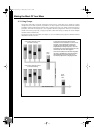
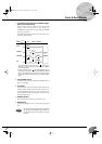
4
Master SEND (AUX1 and AUX2 Controls)
Adjust the signal level, respectively. These are the signals that
are output to the AUX1 and AUX2 SEND jacks.
5
RETURN (AUX1, AUX2, and ST Controls)
•AUX1 and AUX2 Controls
Adjust the level of the mixed L/R signal sent from the
RETURN jacks (L (MONO) and R) to the AUX1 and AUX2
buses.
• ST Control
Adjust the level of the signal sent from the RETURN jacks (L
(MONO) and R) to the Stereo bus.
If you supply a signal to the RETURN L (MONO)
jack only, the mixer outputs the identical signal to
both the L and R Stereo buses.
6
2TR IN Control
Adjusts the level of the signal sent from the 2TR IN jack to the
Stereo bus.
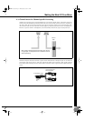
7
PHANTOM +48 V Switch
This switch toggles phantom power on and off. If you set the
switch on, the mixer supplies power to all channels that provide
XLR mic input jacks (CHs 1–8, 9/10, 11/12 on MG16/4, 1–4,
5/6, 7/8 on MG12/4). Set this switch on when using one or
more condenser microphones.
When this switch is on, the mixer supplies DC +48 V
power to pins 2 and 3 of all XLR-type MIC INPUT
jacks.
• Be sure to leave this switch OFF when you are not
using phantom power. Humming or damage may
result if you connect to an unbalanced device or to
an ungrounded transformer while this switch is on.
But note that the switch may be left on without
problem when connecting to balanced dynamic
microphones.
•To avoid damage to speakers, be sure to turn off
amplifiers (or powered speakers) before turning this
switch on or off.
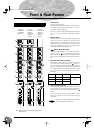
Master Control Section
B
76
A
9
4
3
2
1
5
0
8
NOTE
NOTE
MG12-16.fm Page 20 Thursday, December 11, 2003 9:03 AM