


250/260 Series Friction Loss Chart – English Data (PSI)
Flow (GPM) 5 10 15 20 25 30
1" Hydraulic <1.0 1.0 2.0 3.0 4.0 6.0
1" Electric 4.4 4.5 5.0 5.0 7.0
Note: For optimum sprinkler performance when designing a system, be sure
to calculate total friction loss to ensure sufficient downstream pressure.
Flow rates are recommended not to exceed 5 PSI loss.
250/260 Series Friction Loss Chart – Metric Data (Bar)
Flow (LPM) 20 40 60 80 100
25mm Hydraulic <0,1 0,1 0,1 0,2 0,3
25mm Electric 0,3 0,3 0,3 0,4
*Values are listed in Bar. For kPa values, multiply tabular values by 100.
For Kg/cm
2
values, multiply tabular values by 1,02. Flow rates are
recommended not to exceed 0,35 Bar loss.
250/260 Series Plastic Valves
Worldwide Headquarters
The Toro Company
8111 Lyndale Avenue South
Bloomington, MN 55420
Phone: 952-888-8801
Fax: 952-887-7265
www.toro.com
GB
Form Number: 200-xxxx
©2005 The Toro Company – All Rights Reserved.
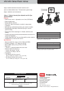
Highly versatile residential/commercial valves for use in
light-to-moderate debris water. Three activation types for easy
design, installation and maintenance.
25mm (1") Electric, Normally Open Hydraulic and Pin-Type
Hydraulic Models
Features
• Manual flow control: adjustable to zero flow (250 Series)
• Manual bleed screw
• Energy-efficient solenoid
• 45cm (18") lead wires (electric models) for easy-access
installation
• Self-cleaning, stainless-steel metering pin (electric models)
• Stainless-steel diaphragm differential spring for smooth,
positive closing
• Single-piece rubber diaphragm for reliable, leak-free valve
closing
• Durable engineering plastic and stainless-steel construction for
exceptional durability
•Tough, glass-filled Zytel
®
cap provides stability under pressure
•Available with or without flow control
Specifications
• Recommended flow range: 19-151 LPM (5-40 GPM)
• Operating pressure: 1.4-10 Bar (20-150 PSI)
• Burst pressure safety rating: 52 Bar (750 PSI)
• Body style:
• 25mm (1") female-threaded inlet and outlet
• Solenoid: 50/60 Hz (24 V.a.c.)
• Inrush: 0.30 Amps, 7.20 VA
• Holding: 0.20 Amps, 4.80 VA
• Dimensions:
• 250 Series (with flow control):
152 x 114mm (H x W) (6" x 4
1
⁄2
") (H x W)
• 260 Series (without flow control):
114 x 114mm (H x W) (4
1
⁄2
" x 4
1
⁄2
") (H x W)
Flow Control Activation Type Thread
Specifying Information
2X0 0X X4
5–w/ Flow Control
6–w/o Flow Control
For Example:
When specifying a 25mm (1") BSP 250 Series Valve with flow control
and pin-type hydraulic activation, you would specify:
0–Pin-Type Hydraulic
1–Normally Open Hydraulic
6–Electric
0–NPT
5–BSP
250-00-54
260-06-04
250-01-04
250-06-04
Effluent flow-control
knob available
(Part No. 89-7855)