


2 Pelco Manual C332M-D (10/98)
REVISION HISTORY
Manual # Date Comments
C332M 9/89 Original version.
C332M-A 10/91 Rev. A. Revised to include model PT573-24R/HB.
C332M-B 5/95 Rev. B. Section 4.4, Connector Assembly, revised. Figures
7-9 revised. to reflect new ground wire color (green). Sec-
tion 6.3, Drive/Chain Maintenance, added. Standardized
voltage references to 120 VAC throughout and changed
applicable specifications.
C332M-C 8/96 Rev. C. Added Figure 1, Table A and Section 7.0. Revised
manual text. Modified Figure 2. Combined wiring sche-
matics into one figure. Deleted model PT573-24R/HB.
C332M-D 10/98 Changed manual to new format. Added certifications. Re-
vised installation instructions. Moved exploded assembly
diagram and parts list to maintenance/service manual.
Revised Troubleshooting and Maintenance sections.
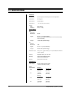
CONTENTS
Section Page
1.0 GENERAL ..................................................................................................3
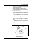
1.1 IMPORTANT SAFEGUARDS AND WARNINGS ...............................3
2.0 DESCRIPTION ..........................................................................................4
2.1 MODELS ............................................................................................4
2.2 OPTIONS ...........................................................................................4
2.3 CERTIFICATIONS .............................................................................4
3.0 INSTALLATION ..........................................................................................5
3.1 MOUNTING .......................................................................................5
3.2 CAMERA/ENCLOSURE MOUNTING ...............................................5
3.3 WIRING .............................................................................................5
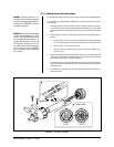
3.3.1 Mating Connector Assembly ....................................................7
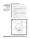
3.4 LIMIT STOP ADJUSTMENTS ...........................................................9
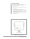
3.5 FRAME SCAN ADJUSTMENT .........................................................10
4.0 OPERATION ..............................................................................................11
5.0 TROUBLESHOOTING ..............................................................................12
5.1 SERVICE MANUAL ..........................................................................12
6.0 MAINTENANCE ........................................................................................13
6.1 TIGHTENING DRIVE CHAINS .........................................................13
6.2 CHAIN DRIVE LUBRICATION ..........................................................13
7.0 SPECIFICATIONS ....................................................................................14
8.0 WARRANTY AND RETURN INFORMATION ...........................................16
LIST OF ILLUSTRATIONS
Figures Page
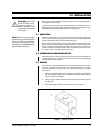
1 Sealant Locations ..............................................................................5
2 Connector Assembly ..........................................................................7
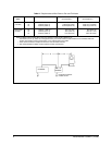
3 PT573R/PT573-24R Wiring Schematic .............................................8
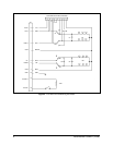
4 PT573R/PT573-24R Series Limit Stop Adjustments .........................9
5Frame Scan Adjustment Location .....................................................10
6 Servicing the Pan/Tilt ........................................................................13
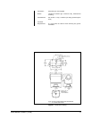
7 Dimension Drawing ........................................................................... 15
LIST OF TABLES
Table Page
A Requirements to Wire Power to Pan and Tilt Motors .........................6