


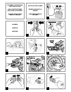

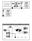
41 • Connect system plug to battery plug. Replace
retaining rod and brush guard/battery door
and secure with safety screw.The vehicle is
ready for use.
VEHICLE FEATURES AND INSTRUCTIONS FOR
USE
42 • A:TOY KEY.This key does not turn your vehicle
on; it is a toy-key.
B: HANDLE.Passengers can use this handle for
additional safety when the vehicle is turned on.
43 • Exclusive SmartPedal Technology™ feature
allows for longer running times and more
realistic driving.When accelerator is pressed
completely down, forward motion is activated.
When pedal is released halfway,coasting action
is engaged. Brake activates automatically when
the child’s foot is removed from the pedal.
44 • TAILGATE:The dump bed features a tailgate
that can be opened by pushing the two red
side levers upwards.
45 • DUMP BED:The dump bed can carry objects for
a maximum of 22 lbs.To operate the dump bed,
pull upward on red latch and unlock it as
shown in the figure.
46 • GEAR LEVER. Gear has three speeds. Push gear
lever downwards to activate rear gear;push it
upwards to activate second gear. NOTE: Only
first and rear gear work when the vehicle has
just been taken out of its package.See steps 47
and 48 to activate second gear.
47 • Unscrew safety screw to release the high speed
lockout pin.
48 • Secure the high speed lockout pin in the
second hole as shown in the figure.The vehicle
can now be shifted to 2nd speed.If you do not
want your child to use the second speed,
secure the high speed lockout pin in the first
hole.
REPLACINGTHE BATTERY
49 • Open battery door following steps 36 - 38.
Remove battery lock as shown in the figure.
50 • Disconnect plugs. Remove battery and replace
it.
51 • Reconnect plugs. Mount battery lock and close
battery lid.WARNING! Make sure battery lid is
always properly fixed with its screw.
52 • Secure battery lock and close battery door.
NOTE:Make sure battery door is always
properly secured with its screw.
BATTERY RECHARGE
WARNING:
WARNING: BATTERY CHARGING
AND ANY OTHER OPERATION ON
THE ELECTRICAL SYSTEM MUST BE
CARRIED OUT BY ADULTS ONLY.
THE BATTERY CAN ALSO BE CHARGED
WITHOUT REMOVING IT FROM THE
VEHICLE.
53 • Disconnect plug A (electrical system) and plug
B (battery).
54 • Connect battery charger to a domestic socket
according to instructions provided.Connect
plug B to plug C (battery charger).
55 • When the battery is ready,disconnect battery
charger from the domestic socket; disconnect
plug C and plug B. Properly fit plug B in plug A.
Always make sure battery lid is properly closed
and secured.
CAUTION:
Only adults should recharge batteries,
never children.
Never allow children to handle
batteries.
Only use the batteries specified by
the manufacturer.
Only use the charger specified by
the manufacturer.
Do not mix old and new batteries.
BATTERY MAINTENANCE
AND SAFETY
ENGLISH
•PEG PEREGO® thanks you for choosing this product.
For over 50 years,PEG PEREGO has been taking
children for an outing: first with its famous baby
carriages and strollers,later with its pedal and
battery operated toy vehicles.
•Read this instruction manual carefully to learn the
use of this vehicle and to teach your child safe and
enjoyable driving.Please keep this manual for use
as a reference in the future.
•Our toys conform with the safety requirements
provided by the Council of the EEC, of the T.Ü.V.; of
the I.I.S.G. Istituto Italiano Sicurezza Giocattoli, and
the U.S. Consumer Toy Safety Specification F963.
Peg Perego S.p.A.is an ISO 9001
certified company.
The fact that we are certified provides
a guarantee of our honesty for our
customers,and fosters trust in the
company’s way of working.
•Peg Perego reserves the right to modify or change
their product.Price, literature,manufacturing
processes or locations or any combination of these
above mentioned entities may change at any time
for any reason without notice with impunity.
Years 3-8
Weight capacity
130 lbs
CAUTION:
ELECTRIC VEHICLE NOT
RECOMMENDED FOR CHILDREN
UNDER 3 YEARS OF AGE. AS WITH
ALL ELECTRIC PRODUCTS,
PRECAUTIONS SHOULD BE
OBSERVED DURING HANDLING
AND USE TO PREVENT ELECTRIC
SHOCK. RECHARGER INCLUDED.120
VOLTS, 60Hz, 30W INPUT, 12 VOLTS
(DC) OUTPUT.
PEG PEREGO offers after-sales services,directly or
through a network of authorized service centers for
repairs or replacement parts.See the back cover of
this instruction manual for contact information.
INITIAL BATTERY RECHARGE
Before riding, charge your battery for
18 hours to initiate them. Failure to
do this can result in permanent
battery damage.
! • Remove battery and charger from packaging.
Connect battery charger to a domestic socket
according to instructions provided.Connect
battery charger to battery.
CAUTION:
ADULT ASSEMBLY REQUIRED.
USE CARE WHEN UNPACKING AS
COMPONENTS TO BE ASSEMBLED
MAY POSE A SMALL PARTS/SHARP
EDGE HAZARD.
BATTERY ALREADY INSTALLED IN
VEHICLE.
CUSTOMER SERVICE
ASSEMBLY INSTRUCTIONS
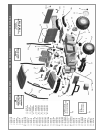
ASSEMBLY
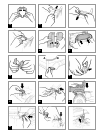
1 • Join the two steering wheel parts.
2 • Apply decal No.22. Align steering wheel on its
bar as shown in the figure.
3 • Attach the steering wheel using the screw and
bolt supplied; make sure to fit the screw in the
circular hole and the bolt in the hexagonal
hole.
4 • Plug toy key into its slot on the dash board.
5 • Apply decal No.6. Attach brush guard: Insert
lower tabs into slots and slide into place over
green pegs.
6 • Secure brush guard using the two screws
supplied.
7 • Apply the chrome decals to the headlights
positions as shown.Attach clear and orange
headlight lenses as shown.
8 • Snap the nut cap into place,and repeat the
operation on the other three wheels.
9 • Snap fuel cap onto its base.
10 • Slide the fuel cap and base into the slot on the
vehicle body, aligning it as shown in the figure.
11 • Rotate it by 90 degrees until it stops.
12 • Split handles - using scissors,if necessary - and
remove the two connecting plastic pieces.
13 • Unscrew the two screws you find on the dump
bed (see figure).Remove plastic bushing. Keep
these screws: you will use them later to attach
the handles.
14 • Snap handles into place as shown in the
picture.
15 •Attach handles with the two screws previously
removed.
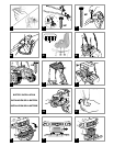
16 • Split mudguards - use scissors,if necessary- and
remove connecting plastic pieces.
17 • Snap mudguards into place on the dump bed.
NOTE:Mudguards must be attached according
to letters printed inside of them: 'L' stands for
'left' and 'R' stands for 'right'.
18 • Split lenses - use scissors,if necessary- and
remove the connecting plastic piece.
19 • Fit tabs in their slots on the mudguards; put in
the external side first (A). Press down on the
inner side (B) to lock lenses in place.
20 • Break connecting parts to remove oval pins
from the dump bed extenders.
21 • Insert dump bed extenders in their housings on
the back of the vehicle.
22 • Secure the dump bed extenders using the
previously removed pins.
23 • Realign the dump bed on the vehicle.
24 • Align rear holes on the dump bed to those of
the dump bed extenders. Secure the dump bed
with the two oval pins previously removed.
25 • Join the spring and red latch as illustrated.Lift
piston and fit red hook in its upper side as
shown in the picture.
26 • Keep piston lifted and align its hole to the rear
hole on the caisson (see figure).
27 • Secure pin in the front hole of the dump bed.
Always make sure that pins are properly
secured.Push the dump bed down.
28 • On both rear canopy poles (without handles),
slide a black collar bracket onto the rounded
end (a). NOTE:Be sure poles and brackets are
positioned as shown in figure.Then secure each
collar bracket with one of the short screws
provided (b). [Find screws for canopy assembly
in secondary hardware bag.]
29 • On each side of the seat, place the pole’s collar
onto the yellow nub.Then secure with the long
screw provided.
30 • Again on both sides of the seat,place the green
handle into position (as shown in the figure)
and secure each handle with the 3 long screws
provided (in main hardware bag).
31 • Align double seat to holes according to the
child's height; secure it from underneath with
the four knobs supplied. Gator has 4 positions
(see figure).
32 • Insert the front poles (with handles) into the
black support brackets on each front fender.
NOTE:Be sure to position both poles so that
they bend outward and go all the way into the
brackets so that the end of the pole is visible
from the underside.
33 • From the underside of fenders,secure each
front pole with the short screw provided.
34 • Attach the green roof piece by pressing down
into place over tops of poles.
35 • Secure roof to poles by using 4 of the short
screws provided.
BATTERY INSTALLATION
36 • Unscrew safety screw on brush guard/battery
door.
37 • Unfasten side flaps pulling them outwards.
38 • Pull brush guard/battery door forward.
39 • Remove the metal retaining rod.
40 • Slide battery into compartment.
59224_PPJDGATHPXSEMAN.qxd:PowerPull_FIUS0502G48 11/18/08 7:43 AM Page 8