


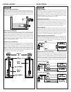
Step Three Step Four
SAFETY PRECAUTIONS INTRODUCTION
About this Manual:
PLEASE READ THE ENTIRE MANUAL PRIOR TO
INSTALLING OR USING THIS PRODUCT. This manual
includes information on all models of Omega’s powered level
switches: LTU-101 series, LVU-150 series, LVC-152 series, LVC-
100 series and LVF-210 series. Please refer to the part number
located on the switch label to verify the exact model which you
have purchased.
User’s Responsibility for Safety:
Omega manufactures a wide range of liquid level sensors and tech-
nologies. While each of these sensors is designed to operate in a
wide variety of applications, it is the user’s responsibility to select
a sensor model that is appropriate for the application, install it
properly, perform tests of the installed system, and maintain all
components. The failure to do so could result in property damage
or serious injury.
Proper Installation and Handling:
Because this is an electrically operated device, only properly-
trained staff should install and/or repair this product. Use a proper
sealant with all installations. Never overtighten the sensor within
the fitting, beyond a maximum of 80 inch-pounds torque. Always
check for leaks prior to system start-up.
Material Compatibility:
The LVU-150, LVC-100 and LVF-210 series sensors are available
in two different wetted materials. Models LVU-150/-152, LVC-
101/-103 and LVF-210/-212 are made of Polypropylene(PP).
Models LVU-151/-153, LVC-102/-104 and LVF-211/-213 are
made of Perfluoroalkoxy(PFA), also known by the trade name
Teflon. The LTU-101 series is made of PP with the forks made of
Ryton (40% glass filled) and the LVC-152 series is made of PP.
Make sure that the model you have selected is compatible with the
application liquid. To determine the chemical compatibility
between the sensor and its application liquids, refer to an industry
reference.
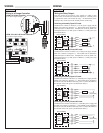
Wiring and Electrical:
The supply voltage used to power the sensor should never exceed
a maximum of 36 volts DC. Electrical wiring of the sensor should
be performed in accordance with all applicable national, state, and
local codes.
Flammable, Explosive and Hazardous Applications:
DO NOT USE THE LTU-101, LVU-150, LVC-152, LVC-100 OR
LVF-210 SERIES GENERAL PURPOSE SWITCH IN HAZ-
ARDOUS LOCATIONS.
WARNING
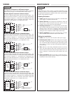
The rating for the relay is 120 VAC/60 VDC @ 1A. For CE
rated applications, the relay rating is 60 VAC/60 VDC @ 1A.
Omega’s powered level switches are not recommended for use
with electrically charged application liquids. For most reliable
operation, the liquid being measured may need to be electrical-
ly grounded.
Vibration Switch:
The Tuning Fork vibration switch operates at a nominal frequency of
400 Hz. As the switch becomes immersed in a liquid or slurry, a cor-
responding frequency shift occurs. When the measured frequency
shift reaches the set point value, the switch changes state indicating
the presence of a liquid or slurry medium.
Do not squeeze the forks together. Doing so could damage or
break the sensor and void the warranty.
When powering up the LTU-101 series, the start-up procedure
requires the switch to cycle through a wet condition for 1/2 second in
order to determine an initial resonance.
Ultrasonic Switch:
The Ultrasonic level switch generates a 1.5 MHz ultrasonic wave
from a miniature piezoelectric transducer located on one side of the
gap in its sensing tip. Another piezo transducer located on the other
side of the gap acts as a microphone, picking up the sound. When liq-
uid enters the gap in the sensing tip, the audio level changes.
The sensor should be installed so that the liquid will drip out of
the gap when the sensor becomes dry.
Optic Switch:
The Optic Leak Detector use principles of optical refraction to detect
the presence or absence of fluid. Apulsed infrared light beam is inter-
nally generated by a light emitting diode and aimed at the slanted
optical tip of the sensor. If the tip is dry, the light beam bounces at a
90 degree angle to a receiving photo transistor, indicating a dry con-
dition. If the tip is immersed in liquid, the light beam will refract out
into the liquid instead of being reflected to the photo transistor, indi-
cating a wet condition.
The Optic Leak Detector can not detect the presence or
absence of specular application liquids that reflect light (such
as milk), or viscous liquids (such as paint) that form a coating
on the sensor tip.
SuperGuard Capacitance Switch:
The SuperGuard level switch generates a pulse-wave radio frequency
signal from the capacitance electrode located in the sensing tip of
each sensor. When liquid comes into contact with the sensing tip, the
capacitance as measured by the sensor changes based on the dielec-
tric constant of the liquid. The guard circuit rejects the negative
effects of coating buildup on the probe by eliminating the coating sig-
nal path between the active and reference electrodes.
Intrusive RF Capacitance Switch:
The Intrusive RF Capacitance level switch generates a 300 kHz pulse-
wave radio frequency signal from the capacitance electrode located in
the sensing tip of each sensor. When liquid comes into contact with
the sensing tip, the capacitance as measured by the sensor changes
based on the dielectric constant of the liquid.
The sensor’s operation may vary based on the dielectric prop-
erties of various application liquids. The LVC-152 series &
LVC-100 series sensor is factory-calibrated to be used with liq-
uids with a dielectric value between 20 and 80.
Liquids with a dielectric constant less than 20 will not
be detected by an LVC-152 series & LVC-100 series sen-
sor, as factory calibrated.