


©
National Instruments Corporation 25 SSR Series Modules and Backplanes
561 Hillgrove Avenue • LaGrange, Illinois 60525 • USA • Phone: (708) 354-1040 • Fax: (708) 354-2820 • http://www.grayhill.com
An ISO-9001 Company
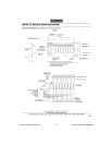
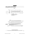
MOUNTING RACKS
55
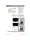
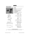
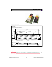
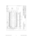
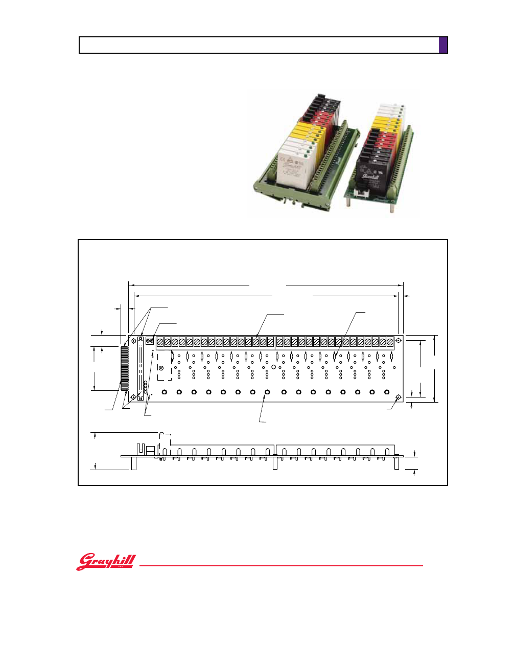
16 MODULE RACK–Standard
Part No. 70RCK16
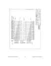
Schematic and Ordering Information on pages 58-59.
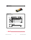
Dimensions are shown in inches (and millimeters).
All tolerances are ± 0.010 (0,25) unless otherwise specified.
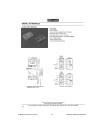
32 31 30 29 28 27 26 25 24 23 22 21 20 19 18 17 16 15 14 13 12 11 10 9 8 7 6 5 4 3 2 1
0 1 2 3 4 5 6 7 8 9 10 11 12 13 14 15
Y
B
W
R
AC INPUT
AC OUTPUT
DC INPUT
DC OUTPUT
+–
14.05 (356,9)
13.55 (344,2)
0.40
(10,2)
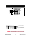
50 PIN EDGE CARD OR HEADER
CONNECTOR FOR LOGIC SIGNALS
(SEE NOTES)
LOGIC SUPPLY
TERMINAL STRIP
FIELD WIRING
TERMINAL STRIP
5 A
FUSE
0.45 (11,4)
2.60 (66,0)
KEY
SLOT
PINS
11/13
PIN 1
USER INSTALLABLE
JUMPER FOR +VCC (2 PLACES)
STATUS LED
STANDOFF I.D. 0.15 (3,8) DIA.
(4 PLACES) CLEARANCE
FOR #6 SCREWS
2.20
(55,9)
MAX.
3.00
(76,2)
3.50
(88,9)
0.25 (6,4)
0.25
(6,4)
0.75 (19,1)