PAGE 4 — STX RIDE-ON TROWEL — PARTS MANUAL — REV. #9 (03/05/10)
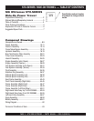
STX-SERIES RIDE-ON TROWEL — TABLE OF CONTENTS
MQ Whiteman STX-SERIES
Ride-On Power Trowel
Proposition 65 Warning .............................................2
Silicosis Warning/Respiratory Hazards ..................... 3
Table of Contents ......................................................4
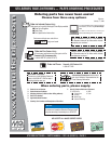
Parts Ordering Procedures ....................................... 5
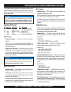
Explanation Of Code In Remarks Column ................ 6
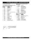
Suggested Spare Parts ............................................. 7
Componet Drawings
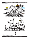
Nameplate and Decals........................................... 8-9
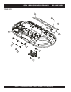
Frame Assembly ................................................ 10-11
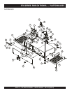
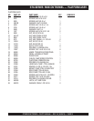
Platform Assembly ............................................. 12-13
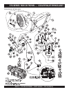
Cooler/Valve Bypass Assembly.......................... 15-15
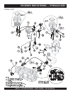
Hydraulic Assembly ............................................ 16-19
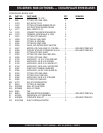
Burp Tank/Suction Filter Assembly .................... 20-21
Pump Levers Assembly ..................................... 22-23
Hose Kit Assembly ............................................. 24-25
Engine Assembly (John Deere) ......................... 26-27
Engine Assembly (Yanmar) ................................ 28-29
Fuel System Assembly (John Deere) ................ 30-31
Fuel System Assembly (Yanmar) ....................... 32-33
Pivot Assembly ................................................... 34-35
Stabilizer Ring Assembly ................................... 36-37
6-Blade Spider Assembly (LH)........................... 38-39
6-Blade Spider Assembly (RH) .......................... 40-41
Seat Frame Assembly ........................................ 42-43
Front Panel Assembly (Right-Side) .................... 44-45
Frame Assembly (Right-Front) ........................... 46-47
Frame Assembly (Right-Rear) ........................... 48-49
Frame Assembly (Left-Front/Rear) .................... 50-51
Right-Hand Valve Assy. Up To S/N 2000885 ...... 52-53
Right-Hand Valve Assy. From S/N 2000886 ....... 54-55
Left-Hand Valve Assembly ................................. 56-57
Spray Assembly ................................................. 58-59
Battery Assembly ............................................... 60-61
Wiring Diagram ....................................................... 62
Terms and Conditions of Sale ................................. 63
Specification and part number
are subject to change without
notice
.
NOTE


