


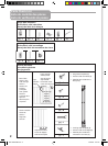
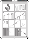

1. Important. Gate must be installed in a
structurally sound opening. The hinge side of
gate must be mounted to a rigid surface.
Ensure mounting surface (wall, door frame,
stairpost, etc.) is strong, rigid and has an even
surface.
If using gate on a stairway, it must be placed on
lowest stair at the bottom.
2. The correct width will be achieved by
adjusting gate sections and all four corner
spindles. Each spindle adjusts individually and
may be extended varying lengths to allow for
molding, uneven walls, etc. Spindles may be
extended a minimum of 11/4” (hinge side) or 1”
(on locking side) and a maximum of 3”.
3. Adjust sections until gate is approximately
the correct width and adjustment holes are
aligned and overlap in two places on both the
top and bottom rail. Gate sections must not be
extended any further than 4 adjustment holes
from spindle ends of gate.
Sections should fit without any distance
between rails or bars.
4. Place screws (i) and screw sockets (j) in top
and bottom sets of overlapping adjustment
holes nearest hinge and locking sides of gate.
Do not fully tighten yet.
5. Screw upper hinge spindle (h) into top rail of
second gate section.
Screw lower hinge spindle (d) into bottom rail of
same side.
Extend spindles equally.
6. Slide locking latch spindle (n) into bottom rail
of main gate section.
Extend spindles equally.
Final spindle adjustments will be made later.
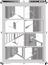
7. Hinge Side Mounting
Screws provided are for mounting directly
into wood. If mounting into brick, drywall or
other surfaces, use appropriate hardware. If
installing into hardwood, (i.e. oak), drilling a
pilot hole may be necessary.
Cut out templates along all dotted lines,
separating template (a) from (b).
Hold template (a) vertically and completely
outstretched against mounting surface with the
end marked “ ” even with the floor.
Mark 4 screw hole positions.
Remove template.
8. Using 2 wood screws (k), mount upper hinge
(g) (with hole pointing up) in top 2 screw hole
positions.
9. Using 2 wood screws (k), mount lower hinge
bottom (c) (with post pointing up) in bottom 2
screw hole positions.
10. Locking Side Mounting
Screws provided are for mounting directly
into wood. If mounting into brick, drywall or
other surfaces, use appropriate hardware. If
installing into hardwood, (i.e. oak), drilling a
pilot hole may be necessary.
Hold template (b) vertically and completely
outstretched against mounting surface with the
end marked “ ” even with the floor.
Mark 4 screw hole positions.
Remove template.
11. Determine which direction the gate should
open. Insert stop pin (o) from behind in hole of
one locking latch bracket (l) opposite desired
opening direction.
Important: The gate cannot open to the stop
pin side.
12. Using 2 wood screws (k) mount locking
latch bracket with stop pin (l) in top 2 screw
hole positions.
Using 2 wood screws (k), mount second locking
latch bracket (l) in bottom 2 screw hole
positions.
13. Push stabilizing foot (r) into vertical tube.
Use of stabilizing foot is optional unless one
or more (maximum 4) optional extensions are
used.
14. Center gate in opening. Adjust upper hinge
spindle (h) so post fits into upper hinge hole (g).
15. Adjust lower hinge spindle (d) so end fits
over lower hinge post (c). Space between end
of gate and mounting surface on hinge side may
be no less than 11/4” and not more than 3”.
16. Adjust locking latch spindles (n) until they
fit securely into both latch brackets. Spindles
must click under locking latch when in the
closed position. Space between end of gate
and mounting surface on locking side may be
no less than 1” and not more than 3”.
Installation
5
Use 1 optional 24” extension (Model G24c) when
opening is 5’ to 7’ wide.
Use 2 optional 24” extensions (Model G24c) when
opening is 7’ to 9’ wide.
Use 3 optional 24” extensions (Model G24c) when
opening is 9’ to 11’ wide,
Use 4 optional 24” extensions (Model G24c) when
opening is 11’ to 13’ wide.
Maximum 4 extensions per gate.
➤
➤
3001-386b-G60.indd 7 27/07/04 9:37:20