


4
Gate Installation
1. Important-Gate must be installed in a
structurally sound opening. The gate must be
mounted to a rigid surface. Ensure mounting
surface (wall, door frame, stairposts, etc.) is
strong, rigid and has an even surface.
2. If using gate on a stairway, it must be placed
either on top stair or on lowest stair at the
bottom. (Figs. 1 & 2)
3. When assembling the gate, it is important
that the sections fit without any distance
between rails or bars. (Fig 3).
4.
FINDING APPROPRIATE WIDTH OF GATE
With the two sections aligned against each
other, place gate against one side of opening
where it is to be installed. The distance between
the opposite side of gate and wall/doorframe
must be between 2” – 4
3
/
4
”. (Fig.3)
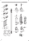
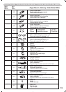
5. Once proper gate width is achieved, place
assembly parts (d1) and (e1) on top gate rail, and
place assembly parts (d2) and (e2) on bottom rail.
Insert screws (f) and screw sockets (g) into all four
assembly fittings according to (Fig 4).
6. Place handle and hinge parts (h), (i), (j) and (k)
onto the gate.
Insert the screws (l) and the screw sockets (m)
into all four parts according to picture. Do not
fully tighten yet. (Fig. 5)
7. HINGE SIDE MOUNTING
Screws provided are for mounting directly
into wood. If mounting into brick, drywall or
other surfaces, use appropriate hardware. If
installing into hardwood (i.e. oak), drilling a
pilot hole may be necessary.
Cut out templates along all dotted lines,
separating template (a) from (b).
Hold template (a) vertically and completely out-
streched against mounting surface with the end
marked " " even with the floor. Mark screw hole
positions. Remove the template. (Fig. 6)
8. Using 2 wood screws (o) mount upper hinge
bracket (n) with the hole and the post pointing
up, in top 2 screw hole positions. Using 2 wood
screws (o) mount lower hinge bracket (p) with
angled side facing down, in bottom 2 screw
hole positions. (Fig. 7)
9. LOCKING SIDE MOUNTING
Screws provided are for mounting directly
into wood. If mounting into brick, drywall or
other surfaces, use appropriate hardware. If
installing into hardwood (i.e. oak), drilling a
pilot hole may be necessary.
Hold template (b) vertically and completely out-
streched against mounting surface with the end
marked " " even with the floor. Mark screw hole
positions. Remove the template. (Fig. 8)
10. Determine which direction the gate should
open. For the top of stairways, gate should
never open out over the stairs. Insert stop pin
(t) into holes of lower locking bracket (s). Insert
stop clip (y) into upper latch (r). (Fig. 9) The
longer portion of the stop pin and the outer
edge of the stop clip should both be on the
same side. Important – The gate cannot open
to the stop pin/stop clip side. Using 2 wood
screws (o) mount lower locking bracket (s) with
hole facing up, in bottom 2 screw hole
positions. Using 2 wood screws (o) install upper
locking bracket (w). Place part (r) onto upper
locking bracket (w). (Fig. 10).
11. Place gate onto hinge parts. Next, place
spring (u) and hinge cap (v) onto upper hinge
bracket post. (Fig 11)
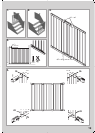
12. IMPORTANT: ENSURE HINGE CAP CAN-
NOT BE PUSHED UP AND IS LOCKED IN
PLACE (Fig. 12)
Center gate in the opening. Loosen screws on
parts (h), (i), (j), and (k) and adjust so they rest
securely into hinge and locking side brackets.
The distance between gate and wall/doorframe
must be between 1” – 2
3
/
8
”. (Fig 13)
If gate is installed on an angle, part (r) will need
to be rotated so that the gate handle rests
securely inside upper locking bracket. (Fig.14)
Once the gate handle rests securely inside
locking bracket, slide locking cap (q) onto upper
locking bracket (w).
IMPORTANT: ENSURE LOCKING CAP
CANNOT BE PUSHED UP AND IS LOCKED IN
PLACE.
Be certain to tighten all gate screws (h), (i), (j)
and (k).