


DISASSEMBLY/ASSEMBLY INSTRUCTIONS
NOTICE
Never apply excessive pressure by a holding device which
may cause distortion of a part.
Apply pressure evenly to parts which have a press fit.
Apply even pressure to the bearing race that will be press
fitted to the mating part.
Use correct tools and fixtures when servicing this tool.
Don’t damage “0” rings when servicing this tool.
Use only genuine ARO replacement parts for this tool. When
ordering, specify part number, description, tool model number
and serial number.
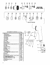
GEARING DISASSEMBLY
Using a wrench on flats of ring gear (30) unthread and remove
ring gear and components.
Remove carrier (28), spindle (29) and gears (26) from ring
gear.
Do not remove bearings (27) unless damage is evident.
Do not remove bearings (31) and spacer (32) unless damage
is evident.
To remove bearings (31) and spacer, press on bearing (31)
from inside splined end of ring gear.
GEARING ASSEMBLY
Assemble one bearing (31) into ring gear, pressing on outer
race of bearing.
Coat shafts of spindle (29) and carrier (28) with ARO 33153
grease.
Assemble gears (26) containing bearings (27) to shafts.
Lubricate gears liberally with ARO 33153 grease (see “Rou-
tine Lubrication Requirements”, page 3).
Assemble spindles and gearing into ring gear. Rotate spindle
and gears to align gear teeth with splines of ring gear.
Assemble spacer (32) and bearing (31) into ring gear, press-
ing on inner race of bearing.
Assemble ring gear and components to tool and tighten, using
a wrench on flats of ring gear.
MOTOR DISASSEMBLY
Remove gearing from tool.
Remove spacer (24) and “0” ring (23)
Tap front edge of housing to remove motor assembly. Locat-
ing pin (25) should also come out.
Grasp cylinder in one hand and tap drive end of rotor (18) with
a soft face hammer; motor will come apart. NOTE: Bearings
are press fit on rotor.
Remove end plate (17) and bearing (16) from rotor.
MOTOR ASSEMBLY
Lubricate bearing (16) with ARO 33153 grease and assemble
to end plate (17) pressing on outer race of bearing.
Assemble end plate (17) to rotor (18) pressing on inner race
of bearing.
Coat five rotor blades (19) with ARO 29665 spindle oil and as-
semble to rotor slots - straight side out.
Coat i.d. of cylinder (20) with ARO 29665 spindle oil and as-
semble over rotor. NOTE: Air inlet slots in end of cylinder must
be aligned with two air inlet holes in end plate (17).
Assemble bearing (22) to end plate (21) pressing on outer
race of bearing.
Assemble end plate (21) to rotor, pressing on inner race of
bearing. Be sure rotor turns without binding.
Insert locating pin (25) into .096” diameter blind hole at bottom
of motor cavity in housing.
Align notches of end plates and cylinder and install motor into
housing, aligning notches with locating pin (25).
Lubricate “0” ring (23) and assemble to end plate (21).
Assemble spacer (24) to motor.
Assemble gearing to tool.
THROTTLE DISASSEMBLY
Remove spirol pin (6) driving it out the left side of housing.
Remove trigger (15), plug (14), valve assembly (13) and “0”
ring (7).
Remove “0” ring (8) valve (9) “0” ring (10) and retaining ring
(11).
Remove inlet adapter (2) and screen (1).
Remove muffler (3) and fillers (4).
THROTTLE ASSEMBLY
Grease and install “0” ring (7).
Assemble retaining ring (11) to valve stem (12).
Grease and assemble “0” ring (10) to valve (9).
Assemble valve (9) to valve stem, with smallest diameter of
valve going on valve stem first.
Grease and assemble “0” ring (8) to valve stem (12).
Assemble valve stem thru plug (14) and assemble plug into
housing (5) aligning .102” diameter holes in housing and
plug.
Assemble trigger (15) to tool, securing with spirol pin (6).
NOTE: Assemble spirol pin from left side of housing.
Assemble fillers (4) and muffler (3) to housing, securing with
inlet adapter (2). .
Clean and replace screen (1) in inlet adapter.
5