


Page 2of 2 650484-X
PUMP OPTION DESCRIPTION CHART
650484-X
PACKING MATERIAL
PLUNGER TYPE
SPRING ARRANGEMENT
(PACKINGS AREUPPER ANDLOWERUNLESS NOTED)
PACKING MATERIAL
SPRING
ARRANGEMENT
4 Multiple Wave Spring w/
316 Stainless Steel Balls
7 Multiple Wave Spring w/
440 Stainless Steel Balls
PLUNGER
TYPE
3 Hardened Stainless Steel w/
Hard Chrome Plating
B Hardened Stainless Steel w/
Ceramic Coating
3 Glass filled PTFE P UHMW-PE / PTFE staggered (upper)
C UHMW-PE UHMW-PE (lower)
G UHMW-PE / Leather staggered R PTFE / UHMW-PE staggered (upper)
PTFE (lower)
X
X
GENERAL DESCRIPTION
WARNING
HAZARDOUS PRESSURE. Do not exceed maxi-
mum operating pressure of 3300 p.s.i. (228 bar) at 150 p.s.i.
(10.3 bar) inlet air pressure.
PUMP RATIO X
INLET PRESSURE TO PUMP MOTOR
=
MAXIMUM PUMP
FLUID PRESSURE
Pump ratiois anexpression of therelationship betweenthe pump motorarea and
the lower pump end area. EXAMPLE:When 150 p.s.i. (10.3 bar) inlet pressure is
suppliedto themotor ofa 6:1ratio pumpit willdevelop amaximum of750 p.s.i.(52
bar) fluid pressure (at no flow)- as the fluid control is opened, the flowrate will in-
crease as the motor cycle rate increases to keep up with the demand.
WARNING
Refer to general information sheet for additional
safety precautions and important information.
x The Two-Ball pumps are primarily designed for the pumping of me-
dium viscosityfluids, StainlessSteel constructionofferscompatibili-
ty with a wide range of fluids. The two-ball design provides better
primingof thelower footvalve. Thedouble actingfeature isstandard
in all ARO industrial pumps, material is delivered to the pump dis-
charge outlet on both the up and down stroke.
x The motor is connected to the lower pump end by a spacer section.
This allows for lubrication of the upper packing gland and prevents
motor contaminationbecause ofnormal wear andeventual leakage
through the material packing gland. Be sure the solvent cup is ade-
quately filled with lubricant to protect the upperpackings and insure
longest service life.
TROUBLE SHOOTING
Pump problems can occur in either the Air Motor Section or the Lower
Pump End Section, use these basic guidelines to help determine which
section is affected.
If the pump will not cycle.
x Becertain tofirst checkfor non-pumpproblemsincluding kinked,re-
strictive or plugged inlet / outlet hose or dispensingdevice. Depres-
surize the pump system and clean out any obstructions in the inlet /
outlet material lines.
x Refer to the motor manual for trouble shooting if the pump does not
cycle and / or air leaks from the air motor.
If the pump cycles but does not deliver material.
x Refer to the lower pump end manual for further trouble shooting.
PUMP CONNECTION -- UPPER / LOWER
NOTE: All threads are right hand.
1. Lay the pump assembly on a workbench.
2. Remove the three nuts from the three spacer rods. (Fig. 1)
3. Pullthe airmotor fromthe lowerpumpend untilmotor pistonrod isin
the “down” position and lower pump end rod is in “up” position.
4. Using e-ringpliers, slide theretaining ring upfar enoughto allow the
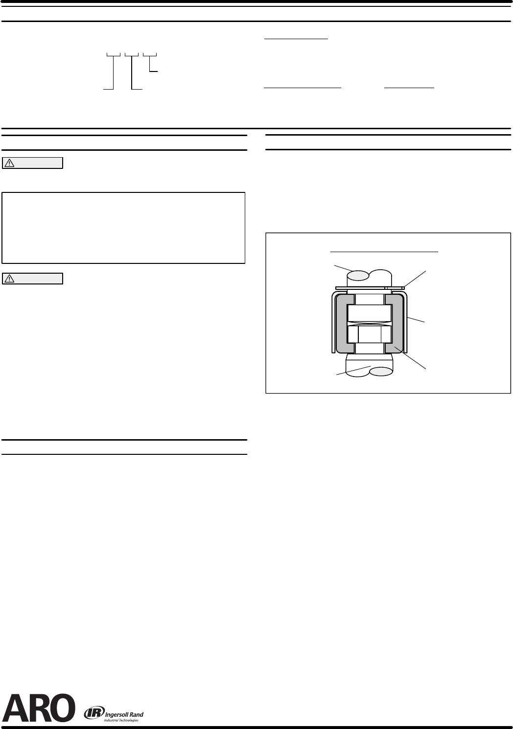
sleeve to move upward and release the two connectors. (Fig. 2)
Lower Pump
Piston Rod
Pump Motor
Piston Rod
RETAINING RING
90102
SLEEVE
90109
CONNECTOR
90096 (2)
PUMP CONNECTOR DETAIL
FIGURE 2
REASSEMBLY
1. Align the pump motor with the lower pump end.
2. Installthe twoconnectorsand retainwith thesleeve, slidethe retain-
ing ring back into position.
3. Reinstall the spacer rods to the pump motor.
4. Bring the motor and lower pump together and retain with the three
nuts.
PN 97999-653